Wiring, Wiring -6, Wiring considerations -6 – Rockwell Automation 1747-BSN Backup Scanner Module User Manual
Page 48: Wiring considerations
Publication 1747-UM010B-EN-P - September 2003
3-6 Installation and Wiring
Wiring
Terminal Wiring
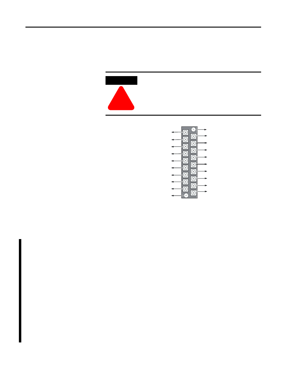
The backup scanner module contains a green removable terminal
block. The terminal pinout is shown on the following page.
Terminal screws accept a maximum of two #14 AWG (2mm 2) wires.
Tighten terminal screws only tight enough to immobilize wires.
Maximum torque on terminal screws is 0.9 Nm (8 in-lbs.).
Wiring Considerations
The system examples on pages 3-7 through 3-9 have been simplified
to show only the type of wiring described. Keep the following
considerations in mind when planning your system:
•
When wiring a system using 1747-BSN backup scanners, you
must connect the High-Speed Serial Link (HSSL) between the
primary and secondary backup scanners. The Local Status Link
(LSL) is required only when more than one 1747-BSN module
per chassis is used.
•
RIO/DH+ connections are dependent upon your system setup
and are mutually exclusive.
•
RS-232 connections are also optional, dependent upon your
system setup.
ATTENTION
!
Disconnect power to the SLC before attempting to
install, remove or wire the removable terminal wiring
block.
Release Screw
HSSL (Line 1- Blue)
HSSL (Shield)
HSSL (Line 2 - Clear)
Release Screw
DH+ (Line 2) to CPU
DH+ (Shield) to CPU
DH+ (Line 1) to CPU
232 (5) / 485 (COM) to CPU
232 (3) / 485 (B) to CPU
232 (2) / 485 (A) to CPU
LSL (Line 2 - Clear)
LSL (Shield)
LSL (Line 1 - Blue)
232 (2) / 485 (A) to Link
232 (3) / 485 (B) to Link
232 (5) / 485 (COM) to Link
RIO / DH+ (Line 1) to Link
RIO / DH+ (Shield) to Link
RIO / DH+ (Line 2) to Link