Status leds, Rs-232/rs-485 network wiring -9, Status leds -9 – Rockwell Automation 1747-BSN Backup Scanner Module User Manual
Page 51
Publication 1747-UM010B-EN-P - September 2003
Installation and Wiring 3-9
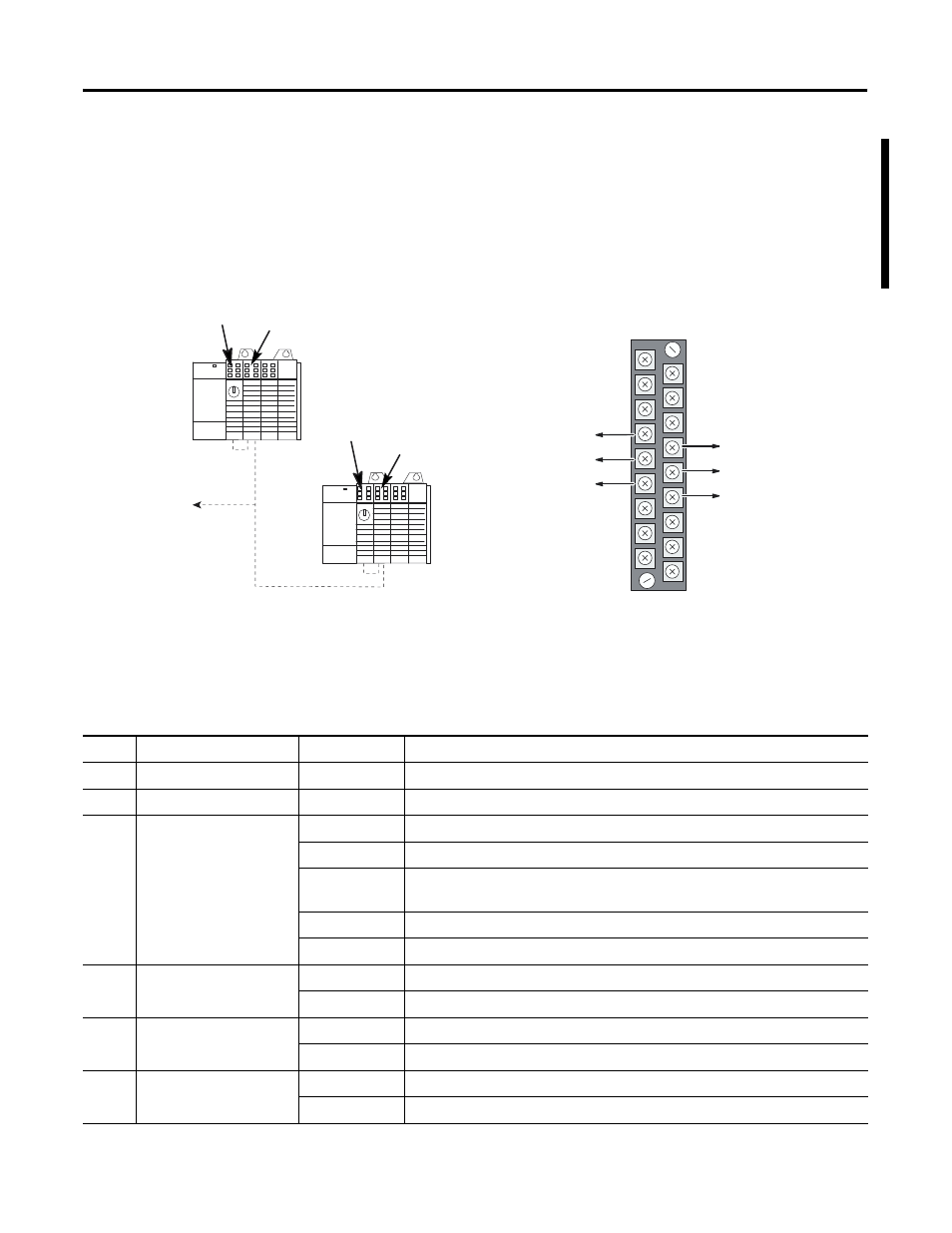
RS-232/RS-485 Network Wiring
The 1747-BSN module supports RS-232 or RS-485 communications for
the primary processor only. The RS-232 or RS-485 network can use the
same BSN module as the DH+ or RIO network.
Figure 3.4 RS-232/485 System
Status LEDs
The table below describes the six LEDs located on the module’s front
panel. To ensure that they are operating correctly, all LEDs are
illuminated during power-up.
Processor
Processor
1747-BSN
1747-BSN
DH485/DF1/ASCII
RS-232/-485 (A) to Link
RS-232/-485 (B) to Link
RS-232/-485 (COM) to Link
RS-232/-485 (A) to CPU
RS-232/-485 (B) to CPU
RS-232/-485 (COM) to CPU
Terminal Block Wiring
LED
Definition
Status & Color
Indication
PRI
Primary
Steady Green
The module is in the primary mode.
SEC
Secondary
Steady Amber
The module is in the secondary mode.
RIO
RIO Communication
Steady Green
The RIO link is working properly.
Flashing Green
A remote device is not configured or connected correctly, or is faulted.
Flashing Red
The RIO link has a fault. The scanner is connected incorrectly, or all devices are
configured improperly, have no power, or are faulted.
Steady Red
There is a configuration error.
Off
The communication channel is not configured as RIO.
ERR
Back-up Module Error
Flashing Red
The module is not ready for switchover.
Off
The module is ready for switchover.
HSSL
High-Speed Serial Link
Communication
Flashing Green
The link is operating with no errors.
Off
A communications error has been detected on the HSSL.
FLT
Fault
Steady Red
A hardware fault has occurred.
Flashing Red
The module is not configured properly.