8 axis synchronisation via can, Axis synchronisation via can, Configuration – Lenze ECSCSxxx User Manual
Page 182
Configuration
Configuring MotionBus/system bus (CAN)
Axis synchronisation via CAN
l
182
EDBCSXS064 EN 4.0
8.1.8
Axis synchronisation via CAN
The CAN interface X4 serves to transfer the CAN sync telegram as synchronisation signal
and the process data.
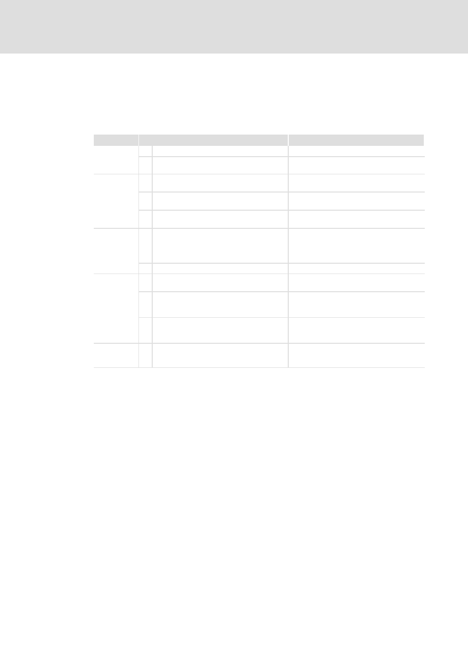
Please observe the following sequence during commissioning:
Device
Step
Description
All devices
1.
Commission the controller and the CAN bus.
2.
Inhibit the drive controllers.
l
Press the
^ 143
Slaves
3.
Connect "CANSync−InsideWindow" with
digital output.
4.
C1120 = 1
Active synchronisation by sync telegram via
CAN bus.
5.
C0366 = 1 (Lenze setting)
CAN sync reaction:
l
Slaves respond to sync telegram.
Master
6.
Define the telegram (identifier) sequence:
A . Send new setpoint to all slaves.
B Send sync telegram.
C Receive response of all slaves.
7.
Start communication/send sync telegrams.
Slaves
8.
Read C0362 from the master.
Retrieve cycle time of the sync telegram from
the master.
9.
Set C1121 according to C0362 of the master.
Adjust the time distance of the sync
telegrams to be received to the cycle time of
the master.
10. Set C1123.
Set optimum size for the "time slot".
l
If the sync signal "jitters" heavily (
^ 179),
Slaves
11. Enable the controller via the signal
"CANSync−InsideWindow" applied to the
digital output.
Synchronisation monitoring:
l
If "CANSync−InsideWindow" = TRUE,
enable the controller.