Function library, Function blocks, 12 analog signal changeover switch (asw) – Lenze EVS9332xS User Manual
Page 86
Function library
Function blocks
3.2.12
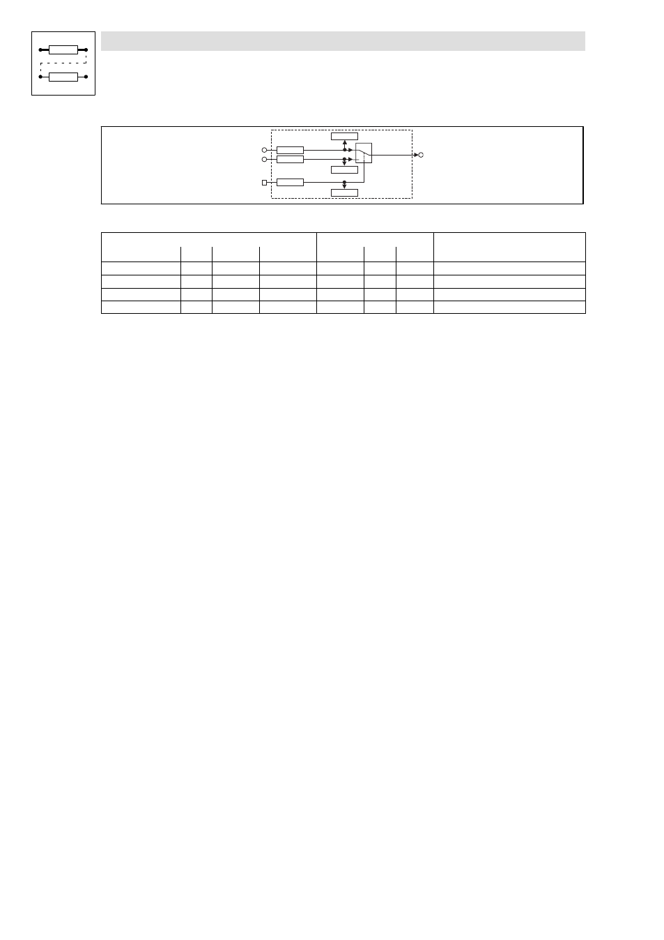
Analog signal changeover switch (ASW)
3−34
l
EDSVS9332S−EXT EN 2.0
A S W 4 - I N 1
C 1 1 6 7 / 1
1
0
C 1 1 6 7 / 2
A S W 4 - S E T
A S W 4 - I N 2
A S W 4
A S W 4 - O U T
C 1 1 6 8
C 1 1 6 5 / 1
C 1 1 6 5 / 2
C 1 1 6 6
Fig. 3−32
Changeover switch for analog signals (ASW4)
Signal
Source
Note
Name
Type
DIS
DIS format
CFG
List
Lenze
ASW4−IN2
a
C1167/1
dec [%]
C1165/1
1
1000
−
ASW4−IN1
a
C1167/2
dec [%]
C1165/2
1
1000
−
ASW4−SET
d
C1168
bin
C1166
2
1000
−
ASW4−OUT
a
−
−
−
−
−
−
Function
This FB is controlled via the binary input. Depending on the input signal, different signals are sent to
the output:
l
If a HIGH signal is applied at the binary input, the signal which is applied at the ASWx−IN2
input is sent to the output.
l
If a LOW signal is applied, the signal which is applied at the ASW−IN2 input is sent to the
output.