Application examples – Lenze EVS9332xS User Manual
Page 244
Application examples
4.2
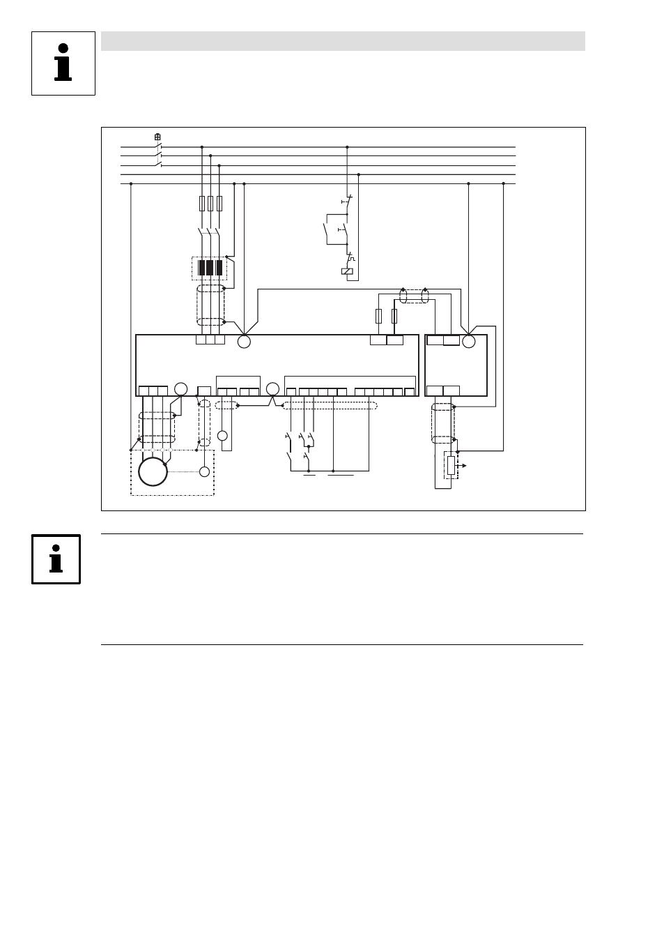
Speed control (C0005 = 1000)
4−6
l
EDSVS9332S−EXT EN 2.0
L 1
L 2
L 3
P E
M
L
K
K 1
M a i n s
c o n t a c t o r
M a i n s s w i t c h
R
X 7
M o t o r
M a i n s f u s e
M a i n s c h o k e
3 ~
X 5
X 6
R F R
L
R
Q S P
2 8
E 1 E 2 E 3 E 4 E 5
A 1 A 2 A 3 A 4 5 9
4
3
2
1
W
V
U
L 3
L 2
L 1
3 9
=
+
-
+ U G
- U G
+ U G - U G
9 3 5 2
9 3 X X
R B
R B 2
R B 1
P E
P E
P E
P E
K 1
K 1
R B
J
N
O F F
O N
K 1
R B
J
F 1
F 2
T R I P - S E T
9300std016
Fig. 4−2
Connection diagram of configuration 1000
Tip!
A braking unit is only required if the DC−bus voltage in the 93XX servo inverter exceeds the upper
switch−off threshold set in C0173 when operating in generator mode (activation of the monitoring
function "OU"). The braking unit prevents "OU" from being activated by converting the kinetic energy
of the machine into heat which prevents the DC−bus voltage from exceeding the upper switch−off
threshold.