Function library, Function blocks – Lenze EVS9332xS User Manual
Page 231
Function library
Function blocks
3.2.63
Multi−axis synchronisation (SYNC1)
3−179
l
EDSVS9332S−EXT EN 2.0
Interpolation cycle time (INTPOL. CYCLE)
The FB interpolates the input signals (C1124, C1125, C1126) between the sync telegrams or sync
signals and transmits them to the corresponding output. This ensures an optimum signal course with
regard to the internal processing cycle (e. g. minimising signal jumps in the output variable when
operating with high sync cycles).
The interpolation is restarted with every sync signal (LOW−HIGH edge).
Code
Value
Function
C1121/2
1 ... 13 ms
Definition of the interpolation cycles/steps
·
C1120 = 1
– C1121/2 has no effect.
– The interpolation cycles are derived from the sync cycle (C1121/1).
·
C1120 = 2
– The interpolation cycle can be selected irrespective of the sync cycle.
– The parameter setting of C1121/2 must be selected according to the cycle of the process value
input.
GND3
GND2
GND1
CANNEL 3
SYNC1-OUT3
[x.x%; 1ms]
CANNEL 2
SYNC1-IN3
[x.x%; 1ms]
CANNEL 1
SYNC - SIGNAL
[10V; 1ms]
T
SYNC
T
INTPOL
9300kur095
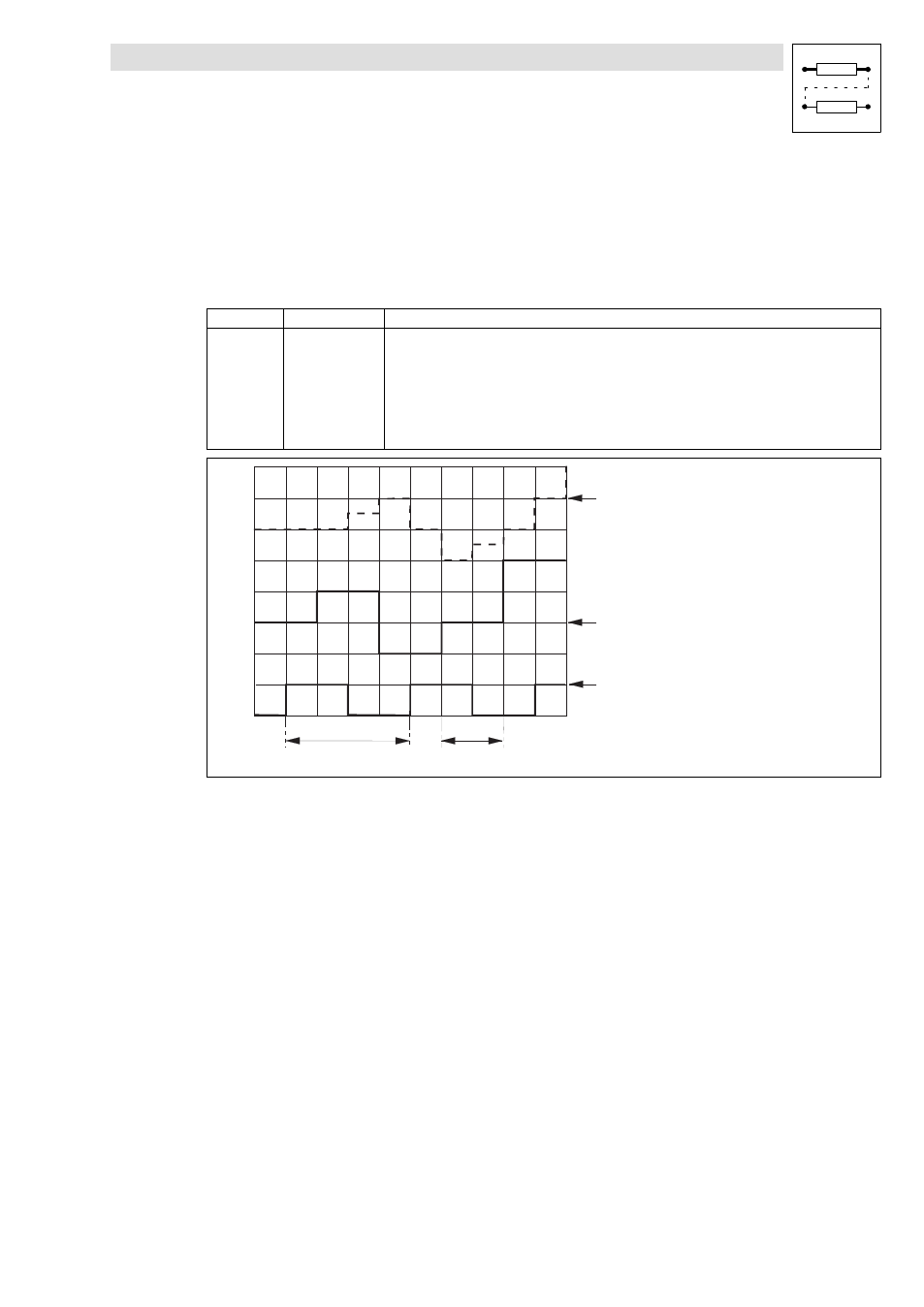
Fig. 3−163
Interpolation example
See Fig. 3−163:
An analog value at SYNC1−IN3 is output as an interpolated value at SYNC1−OUT3.
l
Sync cycle (C1121/1) = 4 ms
l
Interpol. cycle (C1121/2) = process cycle = 2 ms
l
Phase displacement (C1123/1) = 0 ms