Configuration, Basic configurations – Lenze EVS9332xS User Manual
Page 40
Configuration
Basic configurations
2.2.6
Angular synchronism
2−28
l
EDSVS9332S−EXT EN 2.0
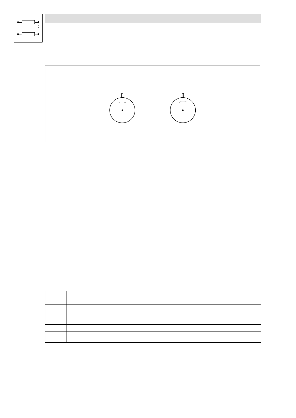
Target situation
Slave
Master
Dö=0
F
F
Dö = phase offset
n = Speed
Fig. 2−4
Target situation for zero pulse processing (
Döā+ā0)
Conditions for reaching the target situation:
l
The function must be activated via code C0534 (function block DFSET)
l
The input DFSET−0−PULSE must be triggered with a HIGH signal when the zero pulse is
evaluated once (function block DFSET)
l
The angle control must be activated (function block MCTRL)
l
The zero pulses must be connected to the Sub−D connectors X9 and X8 (X8 when using an
encoder)
Zero pulse at the setpoint
The set rotor position is specified via the setpoint zero pulse (i.e. when the drive system is running).
It is only synchronised if one setpoint zero pulse and actual zero pulse have occurred before, i.e. not
before the second zero pulse.
Control mode:
The phase offset is compensated via acceleration or deceleration. The direction (acceleration or
deceleration) depends on the detected phase offset. If the rotor is leading in the range from 0 to 180 °,
the drive is synchronised by deceleration. If the rotor is lagging in the range from 0 to 180 °, the drive
is synchronised by acceleration.
Different synchronisation modes
In C0534 you can select between different synchronisation modes.
C0534
Synchronisation mode
1
Continuous synchronisation as described under "Zero pulse at the setpoint" (see page 2−28)
2
Same as selection 1, but DFSET−0−PULSE must be triggered with a LOW−HIGH edge
10
One−time synchronisation; control mode as described under "Zero pulse at the setpoint" (see page 2−28)
11
One−time synchronisation; the drive is always synchronised by clockwise rotation
12
One−time synchronisation; the drive is always synchronised by counter−clockwise rotation
13
One−time evaluation of the setpoint pulse and the actual pulse; the synchronisation direction results from the sign between
setpoint pulse and actual pulse