Angular trimming, Following error limit, Configuration – Lenze EVS9332xS User Manual
Page 39: Basic configurations
Configuration
Basic configurations
2.2.6
Angular synchronism
2−27
l
EDSVS9332S−EXT EN 2.0
2.2.6.2
Angular trimming
The angular trimming can be changed via C0473/3. It is displayed via C0536/3. Angular trimming can
also be carried out via another analog signal source:
l
Analog output of a function block
l
Motor potentiometer
l
Analog terminal
l
Keyboard
l
Automation interface or system bus
The input of the angle trimming can be multiplied in C0529.
This serves to change the rotor position by up to 20000 revolutions:
l
Negative values = CCW offset
l
Positive values = CW offset
Resolution: 65536 inc/rev. = 1 rev. × C0529
2.2.6.3
Following error limit
The absolute value of the following error limit can be set in increments via C0255. The setting range
is: 0 ... 1.8 × 10
9
increments.
When reaching the following error limit, a signal is generated which is evaluated via "Monitoring". This
signal can be evaluated with the priority (TRIP, MESSAGE or WARNING) required by the user.
When setting CINH, the angular difference is set to zero. Thus, neither the signal "following error limit"
is generated any longer.
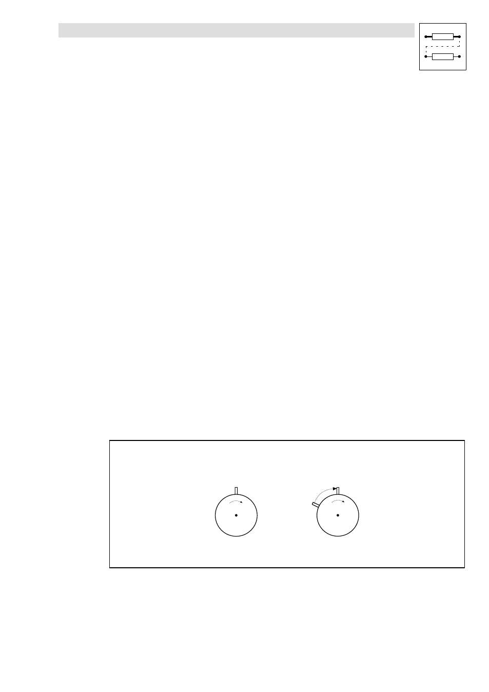
2.2.6.4
Processing of the zero pulse (flying synchronising)
If the zero pulses are not used for the master frequency processing, an angular synchronism with a
constant phase offset is achieved.
Initial situation
Slave
Master
Dö
Dö = phase offset
F
F
n = Speed
Fig. 2−3
Initial situation for zero pulse processing (
Döā0ā0)
If this phase offset is to be corrected to 0, either
l
homing is required or
l
the zero pulses of the master frequency input and the feedback system are to be processed.