Control terminals, Important notes, Electrical installation – Lenze EVF9333 User Manual
Page 199: Stop
Electrical installation
Control terminals
Important notes
l
199
EDKVF9333V DE/EN/FR 7.1
5.8
Control terminals
5.8.1
Important notes
(
Stop!
The control card will be damaged if
ƒ
the voltage between X5/39 and PE or X6/7 and PE is greater than 50 V,
ƒ
the voltage between voltage source and X6/7 exceeds 10 V (common mode)
in case of supply via external voltage source.
Limit the voltage before switching on the drive controller:
ƒ
Connect X5/39, X6/2, X6/4 and X6/7 directly to PE or
ƒ
use voltage−limiting components.
ƒ
For trouble−free operation, the control cables must be shielded:
– Connect the shield of digital input and output cables at both ends.
– Connect the shield of analog input and output cables at one end (at the drive
controller).
– For lengths of 200 mm and more, use only shielded cables for analog and digital
inputs and outputs. Under 200 mm, unshielded but twisted cables may be used.
Installation material required from the scope of supply:
Description
Use
Quantity
Shield sheet
Shield connection for control cables
1
Screw M4 × 10 mm (DIN 7985)
Shield sheet fastening
1
Terminal strip, 4−pole
(only for variants V004 and V024)
Connection of safety relay K
SR
at X11
1
Terminal strip, 7−pole
Connection of digital inputs and outputs at X5
2
Terminal strip, 4−pole
Connection of analog inputs and outputs at X6
2
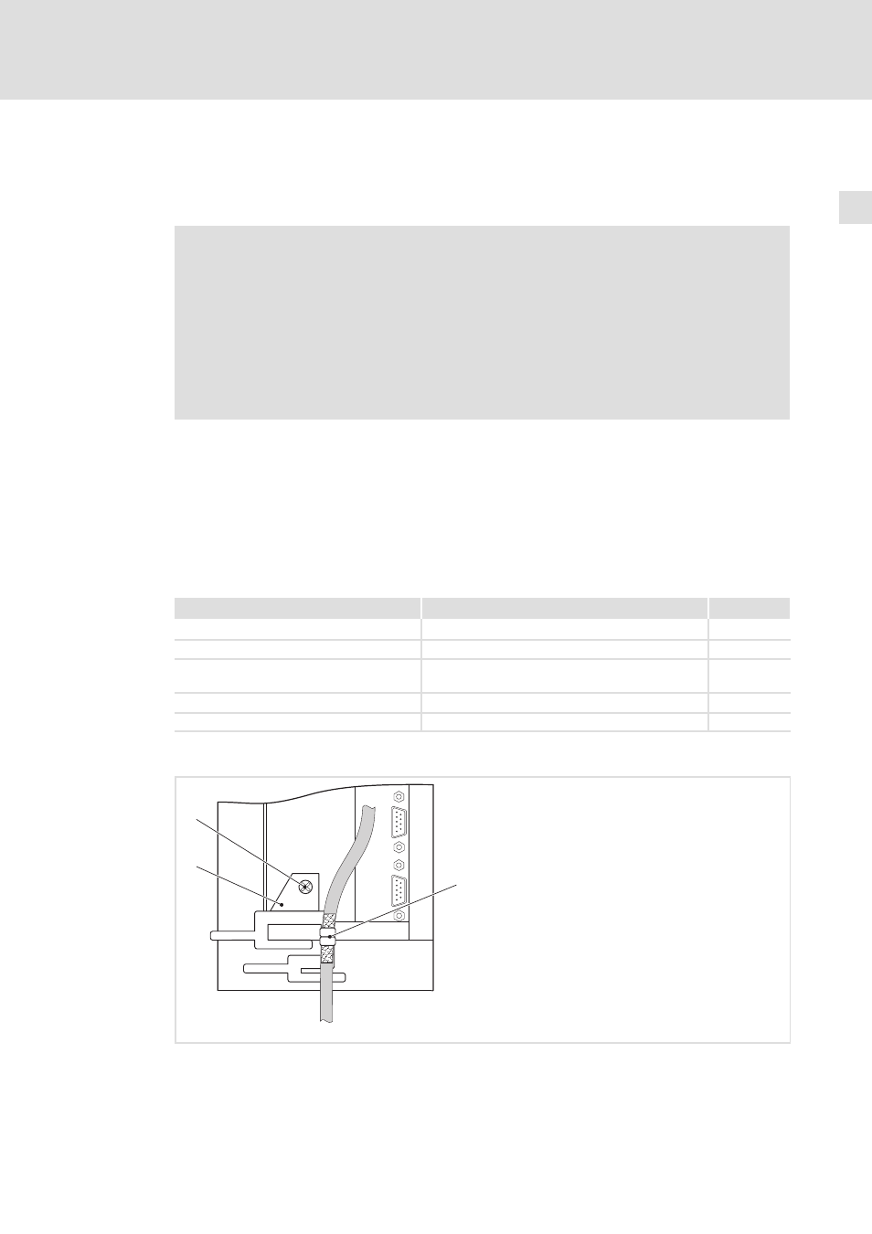
How to connect the shield
1
2
0
9300vec129
Fig. 5−25
Connection of cable shield to shield sheet
0 Shield sheet
1 Fasten shield sheet with M4 × 10 mm screw at the bottom of the control card
2 Securely clamp cable shield with lugs