Electrical installation – Lenze EVF9333 User Manual
Page 180
Electrical installation
Standard devices in the power range 15 ... 30 kW
Motor connection
l
180
EDKVF9333V DE/EN/FR 7.1
PE
PE
T1
T1
T2
T2
U
V
W
4
4
T1
T2
2.5 Nm
22,1 lb-in
T1
T2
2.5 Nm
22,1 lb-in
}
+
PE
}
+
PE
0
0
1
1
3
2
2
U, V, W,
PE
5 Nm
44 lb-in
M 6
9300std030
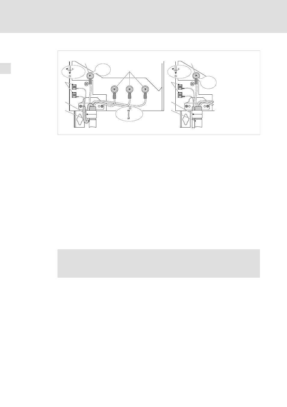
Fig. 5−12
Motor connection with PTC thermistor or thermal contact (NC contact)
0 Motor connection with Lenze system cable with integrated control cable for the motor
temperature monitoring
1 Shield sheet
Clamp entire shield and shield of the control cable for the motor temperature monitoring
with the straps. If required, fix by means of cable tie.
0 Motor cable connection and separate control cable for the motor temperature monitoring
1 Shield sheet
Clamp shield of the motor cable and shield of the cable for the motor temperature
monitoring with the straps. If required, fix by means of cable tie.
2 PE stud
PE cable connection with ring cable lug
3 U, V, W
Motor cable connection
Check the correct polarity. Observe maximum length of the motor cable.
Max. connectable cable cross−section: 50 mm
2
with ring cable lug
4 T1, T2 for motor temperature monitoring
Cable connection for PTC thermistors or thermal contacts (NC contacts)
Motor with KTY thermal sensor
)
Note!
ƒ
We recommend to use Lenze system cables for wiring.
ƒ
For self−made cables only use cables with shielded cores twisted in pairs.