Electrical installation, Motor with kty thermal sensor, We recommend to use lenze system cables for wiring – Lenze EVF9333 User Manual
Page 196
Electrical installation
Standard devices in the power range 75 ... 90 kW
Motor connection
l
196
EDKVF9333V DE/EN/FR 7.1
Characteristics of the connection for motor temperature monitoring:
Terminals T1, T2
Connection
l
PTC thermistor
– PTC thermistor with defined tripping temperature (acc. to DIN 44081 and
DIN 44082)
l
Thermal contact (NC contact)
– Thermostat as NC contact
Tripping point
l
Fixed (depending on the PTC/thermal contact)
l
PTC: R
J
>
1600
W
l
Configurable as warning or error (TRIP)
Notes
l
Monitoring is not active in the Lenze setting.
l
If you do not use a Lenze motor, we recommend the use of a PTC thermistor up
to 150°C.
T1
T2
PE
U
V
W
2
3
4
M4 x 12: 2.5 Nm (22.1 lb-in)
M5 x 12: 3 Nm (26.5 lb-in)
U, V, W,
PE
M10
30 Nm
264 lb-in
1
0
T1
T2
2.5 Nm
22.1 lb-in
5
}
+
PE
9300std032
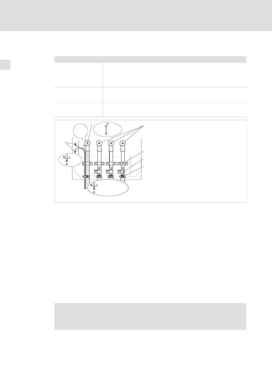
Fig. 5−22
Motor connection with PTC thermistor or thermal contact (NC contact)
0 PE stud
PE cable connection with ring cable lug
1 U, V, W
Motor cable connection
Check the correct polarity. Observe maximum length of the motor cable.
Max. connectable cable cross−section: 240 mm
2
with ring cable lug
2 Cable clamps for strain relief of motor cable
Fasten cable clamps with M4 × 12 mm screws
3 Shield clamps
Place shields of motor cable with large surface on the shield sheet and fasten with shield
clamps and M5 × 12 mm screws
4 Cable ties for additional strain relief of motor cable
5 T1, T2 for motor temperature monitoring
Cable connection for PTC thermistors or thermal contacts (NC contacts)
Place shield with large surface on PE stud
Motor with KTY thermal sensor
)
Note!
ƒ
We recommend to use Lenze system cables for wiring.
ƒ
For self−made cables only use cables with shielded cores twisted in pairs.