Electrical installation – Lenze EVF9333 User Manual
Page 179
Electrical installation
Standard devices in the power range 15 ... 30 kW
Motor connection
l
179
EDKVF9333V DE/EN/FR 7.1
PE U
V
W
T1 T2
+UG -UG
PES
PES
PE
M
3~
J>
PES
PES
PES
2.7 k
MONIT-OH8
15 V
3.3 k
7.4 k
9300vec139
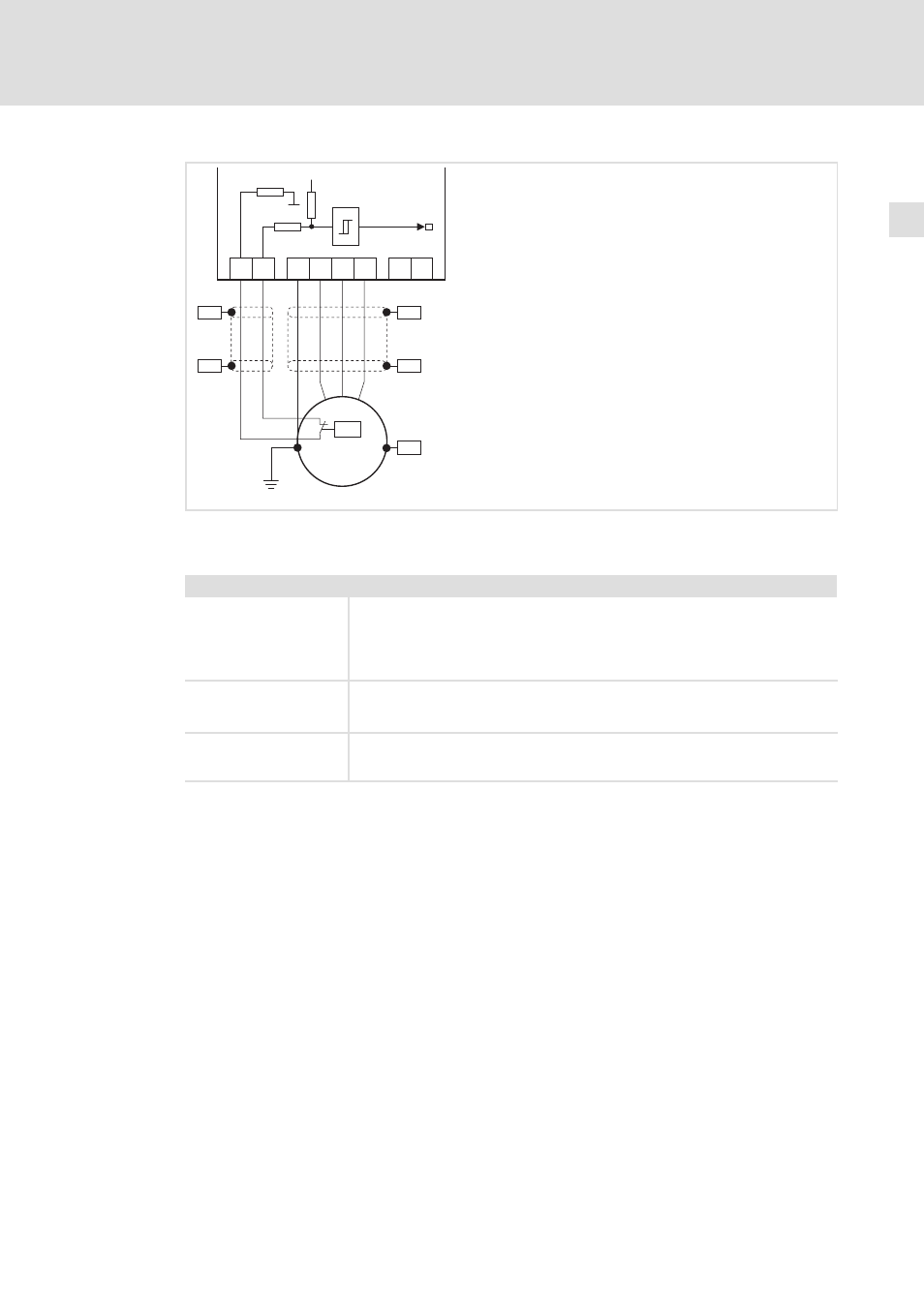
Fig. 5−11
Circuit diagram of motor connection with PTC thermistor or thermal contact (NC contact) at T1, T2
Characteristics of the connection for motor temperature monitoring:
Terminals T1, T2
Connection
l
PTC thermistor
– PTC thermistor with defined tripping temperature (acc. to DIN 44081 and
DIN 44082)
l
Thermal contact (NC contact)
– Thermostat as NC contact
Tripping point
l
Fixed (depending on the PTC/thermal contact)
l
PTC: R
J
>
1600
W
l
Configurable as warning or error (TRIP)
Notes
l
Monitoring is not active in the Lenze setting.
l
If you do not use a Lenze motor, we recommend the use of a PTC thermistor up
to 150°C.