Motor connection, Electrical installation, Stop – Lenze EVF9333 User Manual
Page 169
Electrical installation
Standard devices in the power range 0.37 ... 11 kW
Motor connection
l
169
EDKVF9333V DE/EN/FR 7.1
5.4.5
Motor connection
)
Note!
ƒ
Fusing the motor cable is not required.
ƒ
The drive controller features 2 connections for motor temperature
monitoring:
– Terminals T1, T2 for connecting a PTC thermistor or thermal contact
(NC contact).
– Pins X8/5 and X8/8 of the incremental encoder input (X8) for connecting a
KTY thermal sensor.
Shield sheet installation
(
Stop!
ƒ
To avoid damaging the PE stud, always install the shield sheet and the PE
connection in the order displayed. The required parts are included in the
accessory kit.
ƒ
Do not use lugs as strain relief.
PE
U V W
T1T2
M6
M5
a
1.7 Nm
15 lb-in
PE
M5
3.4 Nm
30 lb-in
}
+
PE
a
2 3
4 5
6 7
1
0
2
4
7
8
0
9300vec128
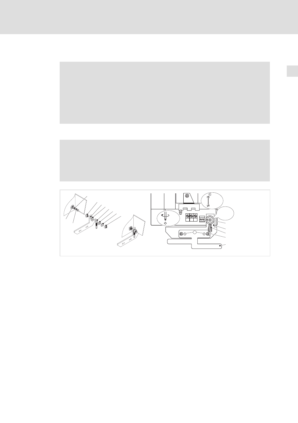
Fig. 5−4
Installation of shield sheet for drive controllers 0.37 ... 11 kW
0 PE stud
1 Screw on M5 nut and tighten hand−tight
2 Slide on fixing bracket for shield sheet
3 Slide on serrated lock washer
4 Slide on PE cable with ring cable lug
5 Slide on washer
6 Slide on spring washer
7 Screw on M5 nut and tighten it
8 Screw shield sheet on fixing bracket with two M4 screws (a)