Message format – IDEX Health & Science VS-606V7 Series User Manual
Page 95
95
•
Message format
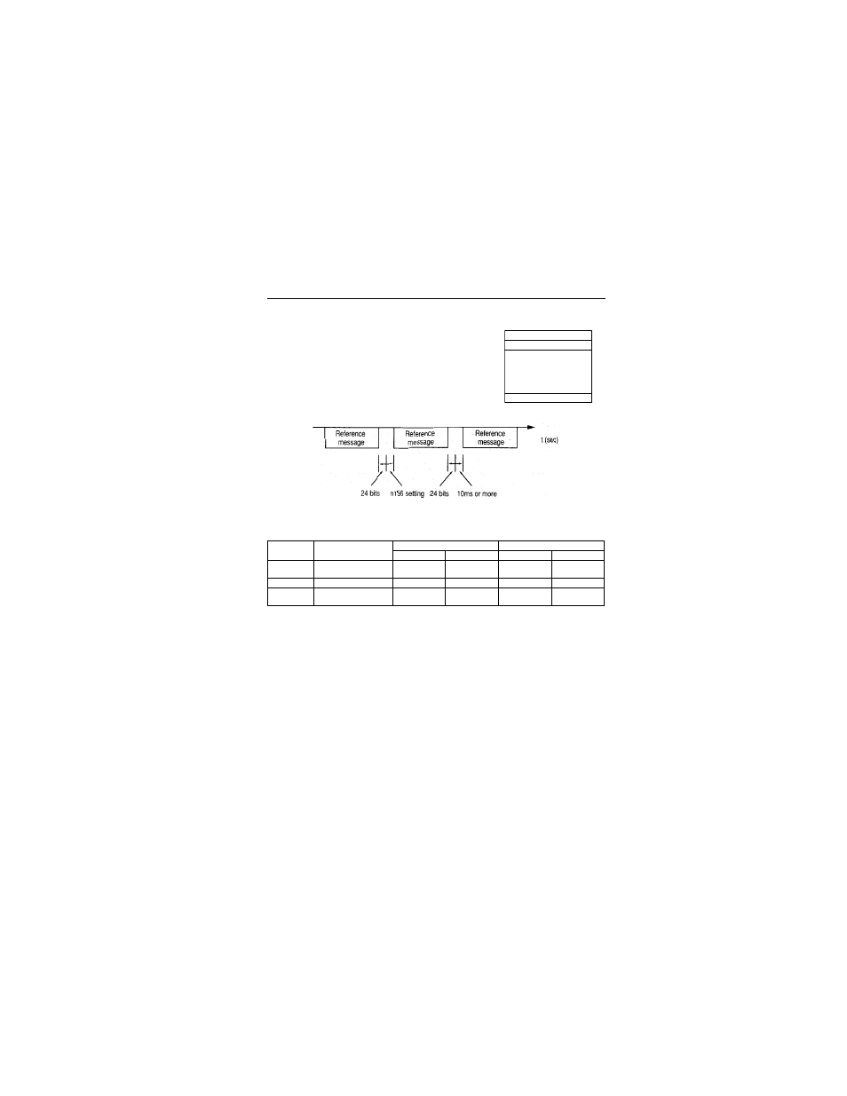
For communications, the master (PLC) sends a command
to the slave (VS-606V7) and the slave responds to it. The
configuration for sending and receiving is as shown to the
right. The length of the data varies according to the
contents of commands (functions).
The interval between messages must be maintained at the
following amount.
•
Slave address: Inverter address (0 to 32). Setting to 0 indicates simultaneous
broadcasting. The inverter does not respond to the command from the master.
•
Function code: Command codes (See below).
•
Data: Composes a series of data by combining holding register numbers (test codes
for loop-back numbers) and their data. Data length depends on the contents of the
commands.
•
Error check: CRC-16 (Calculate the value by the following method.)
1. The default value at calculation of CRC-16 is normally 0. In the MEMOBUS
system, change the default to 1 (all 1 to 16-bit).
2. Calculate CRC-16 assuming that the loop address LSB is MSB and the last data
MSB is LSB.
3. Also calculate CRC-16 for a response message from the slave and refer it to
CRC-16 in the response message.
Function
Code
Function
Reference Message
Response Message
Minimum (Byte) Maximum (Byte) Minimum (Byte) Maximum (Byte)
01H
Reading holding
resistor contents
8
8
7
37
08H
Loop back test
8
8
8
8
10H
Write in several
holding resistors
11
41
8
8
Slave address
Function code
Data
Error Check
VS-606V7 VS-606V7 VS-606V7