2 accessing the e buffer, Cs8422 – Cirrus Logic CS8422 User Manual
Page 68
68
DS692F2
CS8422
There are a number of conditions that will inhibit the buffer update. If the CS_UPDATE bit in
is set to ‘0’, the only condition that will inhibit the update is PLL phase unlock. If the CS_UPDATE
bit in
is set to ‘1’, a biphase, confidence, parity, or CRC error will also inhibit the
update.
12.4.2
Accessing the E buffer
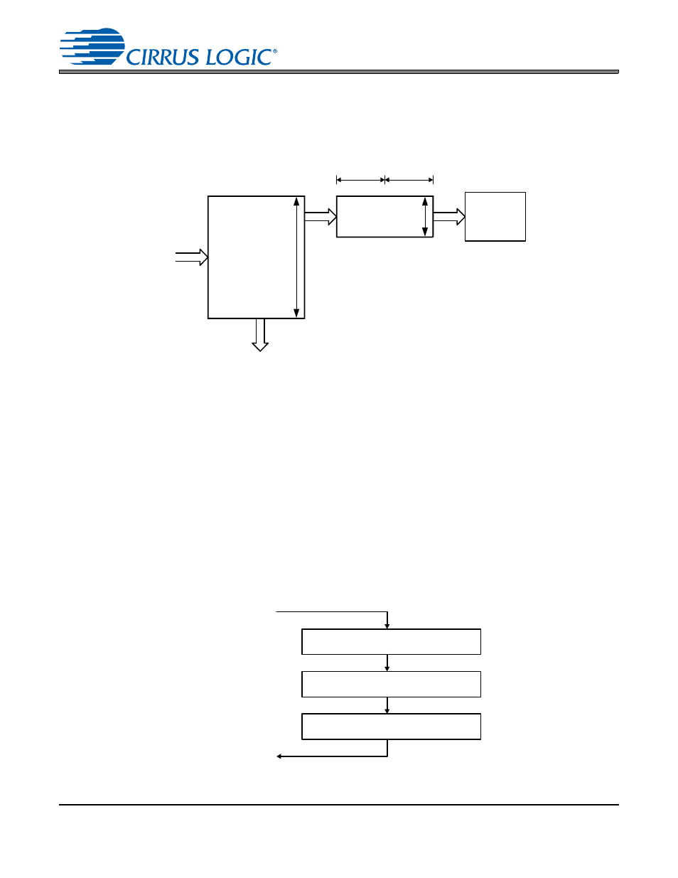
The user can monitor the incoming data by reading the E buffer, which is mapped into the register space of
the CS8422, through the control port.
The user can configure the interrupt enable register to cause interrupts to occur whenever D to E buffer
transfers occur. This allows determination of the allowable time periods to interact with the E buffer.
Also provided is a D to E inhibit bit in the
register. This may be used whenever
“long” control port interactions are occurring or for debugging purposes.
A flowchart for reading the E buffer is shown in
. Since a D to E interrupt occurs just after reading,
there is a substantial time interval until the next D to E transfer (approximately 192 frames worth of time).
This is usually enough time to access the E data without having to inhibit the next transfer.
From
AES3
Receiver
E
8-bits
8-bits
A
B
D
Received
Data
Buffer
5 words
C Data Serial Output
Control
Port
Registers
24 words
Figure 34. Channel Status Data Buffer Structure
D to E interrupt occurs
Optionally set D to E inhibit
Read E data
If set, clear D to E inhibit
Return
Figure 35. Flowchart for Reading the E Buffer