1 hardware mode serial audio port control, Table 3. hardware mode control settings, Cs8422 – Cirrus Logic CS8422 User Manual
Page 41
DS692F2
41
CS8422
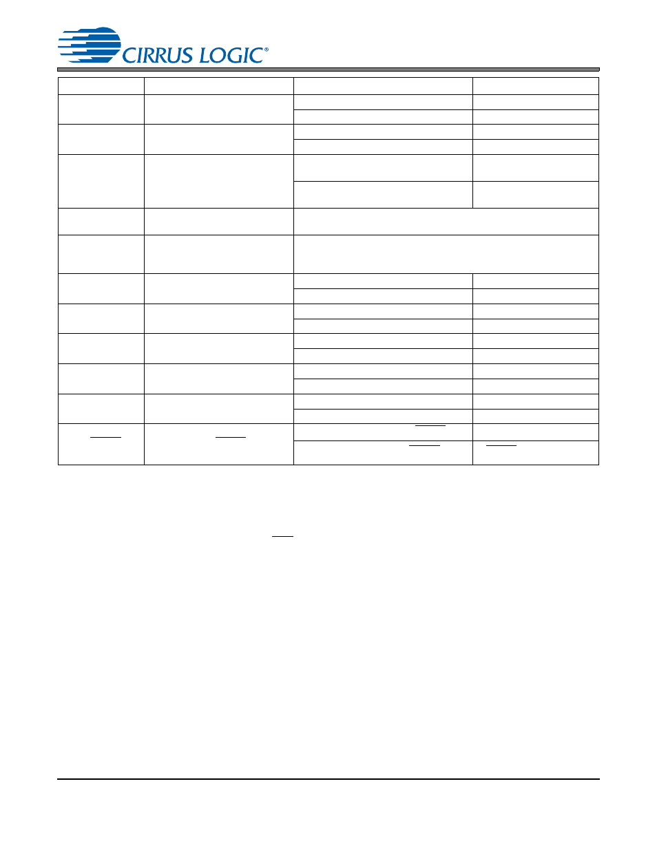
Table 3. Hardware Mode Control Settings
8.1
Hardware Mode Serial Audio Port Control
The CS8422 uses the resistors attached to the MS_SEL and SAOF pins to determine the modes of opera-
tion for its serial output ports. After RST is released, the resistor value and condition (VL or GND) are
sensed. This operation will take approximately 4 ms to complete. The SRC_UNLOCK pin will remain high
and both SDOUT pins will be muted until the mode detection sequence has completed. After this, if all clocks
are stable, SRC_UNLOCK will be brought low when audio output is valid and normal operation will begin.
The resistor attached to each mode selection pin should be placed physically close to the CS8422. The end
of the resistor not connected to the mode selection pins should be connected as close as possible to VL and
GND to minimize noise.
show the pin functions and their corresponding settings.
shows the Hardware Mode options for output serial port format and the required SAOF pin config-
urations. In the case of SDOUT2, the output resolution depends on the resolution of the incoming AES3-
compatible data. In Right-Justified Modes, the serial format word-length will be equal to the AES3 input data
resolution. The exception is the case where Right-Justified Mode is selected and the AES3 input word-
length is an odd number of bits. In this case, the SDOUT2 word-length will be zero-stuffed to be 1 bit longer
then the AES3 input word-length (example: a 19-bit AES3 input word will result in an 20-bit right-justified
serial format). For a more detailed description of serial formats, refer to
.
shows the Hardware Mode master/slave and clock options for both serial ports, and the required
MS_SEL pin configurations. For SDOUT1, when the serial port is set to master mode, the master clock ratio
Pin Name
Description
Pin Configuration
Selection
RX_SEL
Selects Active AES3 RX Input
Connected to GND
RXP0/RXN0 is active
Connected to VL
RXP1/RXN1 is active
TX_SEL
Selects RX Input to be output on
TX pin
Connected to GND
RXP0/RXN0 to TX
Connected to VL
RXP1/RXN1 to TX
SDOUT1
Enables or Disables De-emphasis
Auto-detect
No pull-up on SDOUT1
De-emphasis Auto-detect
Enabled
20 k
pull-up on SDOUT1
De-emphasis Auto-detect
Disabled
SAOF
Selects data format for SDOUT1
& SDOUT2
MS_SEL
Selects master/slave and clock
configuration for SDOUT1&
SDOUT 2
RMCK
Selects master clock source for
SDOUT1 serial port
No pull-up on RMCK
XTI-XTO
20 k
pull-up on RMCK
RMCK
MCLK_OUT
Selects master clock source for
the SRC
No pull-up on MCLK_OUT
Ring Oscillator
20 k
pull-up on MCLK_OUT
PLL Clock
TX/U
Selects TX pass-through output or
incoming U data output
No pull-up on U
TX Pass-through
20 k
pull-up on U
U Data Output
C
Selects Software or Hardware
Mode
No pull-up on C
Software Mode
20 k
pull-up on C
Hardware Mode
NV/RERR
Selects error signal output on
NV/RERR
No pull-up on RERR/NVERR
NVERR
20 k
pull-up on RERR/NVERR
RERR
V/AUDIO
Selects either incoming Validity
data output or AUDIO indicator
output
20 k
pull-down on V/AUDIO
Validity data output
20 k
pull-up on V/AUDIO
AUDIO indicator output