2 isolating transformer requirements, 4 channel status buffer management, 1 aes3 channel status (c) bit management – Cirrus Logic CS8422 User Manual
Page 67: Figures 32, Illus, Cs8422
DS692F2
67
CS8422
12.3.2
Isolating Transformer Requirements
Please refer to the application note AN134: AES and SPDIF Recommended Transformers for resources on
transformer selection
12.4
Channel Status Buffer Management
12.4.1
AES3 Channel Status (C) Bit Management
The CS8422 contains sufficient RAM to store the first 5 bytes of C data for both A and B channels (5 x 2 x 8
= 80 bits). The user may read from this buffer’s RAM through the control port.
The buffering scheme involves two buffers, named D and E, as shown in
. The MSB of each byte
represents the first bit in the serial C data stream. For example, the MSB of byte 0 (which is at control port
address 23h) is the consumer/professional bit for channel status block A.
The first buffer (D) accepts incoming C data from the AES receiver. The 2nd buffer (E) accepts entire blocks
of data from the D buffer. The E buffer is also accessible from the control port, allowing reading of the first
five bytes of C data.
The complete C data may be obtained through the C pin in Hardware Mode and through one of the GPO
pins in Software Mode. The C data is serially shifted out of the CS8422 clocked by the rising and falling
edges of OLRCK or VLRCK.
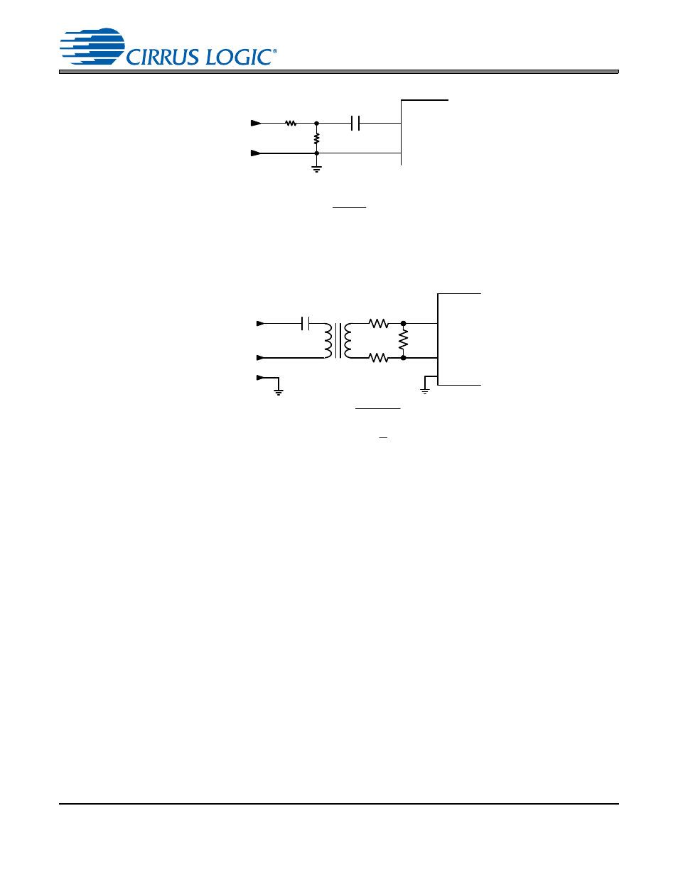
RX
.01
F
CS8422
AGND
R1
R2
V
in
+
-
R2 =
247.5
V
in
R1 = 75 – R2
75
Coax
(1)
(2)
Figure 32. Receiver Input Attenuation – Single-ended Input
110
Twisted
Pair
CS8422
RXP
RXN
R
in
R
in
R
AGND
V
in+
V
in-
(1) R =
726
V
in+
- V
in-
(2) R
in
= 55 - R
2
Figure 33. Receiver Input Attenuation – Differential Input