Table 4, Table 5, Shows th – Cirrus Logic CS8422 User Manual
Page 42: Cs8422
42
DS692F2
CS8422
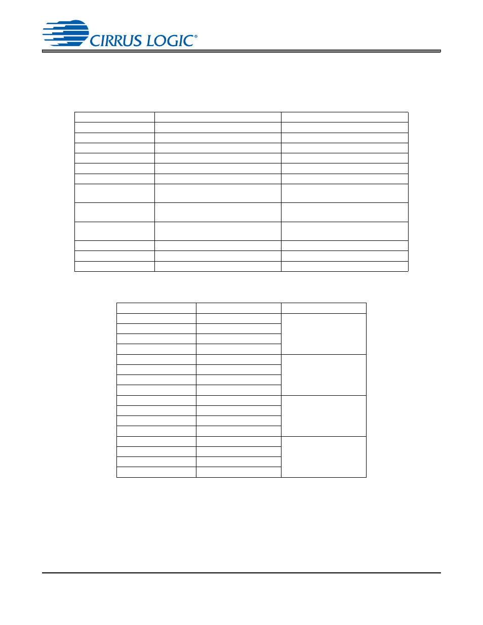
determines what the output sample rate will be based on the MCLK selected for SDOUT1, as shown in the
hardware control pin descriptions shown above. For SDOUT2, the output sample rate is dictated by the in-
coming AES3 data, and the master mode clock ratio determines the frequency of RMCK relative to the in-
coming AES3 sample rate. Note: if TDM Mode is selected for SDOUT1, then SDOUT1 cannot be set to
“Master, Fso = MCLK/128”.
SAOF pin
SDOUT1 Data Format
SDOUT2 Data Format
32.4 k
± 1% to GND
I²S 24-bit data
I²S
16.2 k
± 1% to GND
I²S 20-bit data
I²S
8.06 k
± 1% to GND
I²S 16-bit data
I²S
4.02 k
± 1% to GND
Left-Justified 24-bit data
Left-Justified
1.96 k
± 1% to GND
Left-Justified 20-bit data
Left-Justified
1.0 k + 1% to GND
Left-Justified 16-bit data
Left-Justified
32.4 k
± 1% to VL
Right-Justified 24-bit data
(Master mode only)
Right-Justified
(Master mode only)
16.2 k
± 1% to VL
Right-Justified 20-bit data
(Master mode only)
Right-Justified
(Master mode only)
8.06 k
± 1% to VL
Right-Justified 16-bit data
(Master mode only)
Right-Justified
(Master mode only)
4.02 k
± 1% to VL
TDM Mode 24-bit data
I²S
1.96 k
± 1% to VL
TDM Mode 20-bit data
I²S
1.0 k + 1% to VL
TDM Mode 16-bit data
I²S
Table 4. Hardware Mode Serial Audio Format Control
MS_SEL pin
SDOUT1
SDOUT2
127.0 k
± 1% to GND
Slave
Slave
RMCK = 256 x Fsi
63.4 k
± 1% to GND
Master, Fso = MCLK/128
32.4 k
± 1% to GND
Master, Fso = MCLK/256
16.2 k
± 1% to GND
Master, Fso = MCLK/512
8.06 k
± 1% to GND
Slave
Master Mode,
RMCK = 128 x Fsi
4.02 k
± 1% to GND
Master, Fso = MCLK/128
1.96 k
± 1% to GND
Master, Fso = MCLK/256
1.0 k + 1% to GND
Master, Fso = MCLK/512
127.0 k
± 1% to VL
Slave
Master Mode,
RMCK = 256 x Fsi
63.4 k
± 1% to VL
Master, Fso = MCLK/128
32.4 k
± 1% to VL
Master, Fso = MCLK/256
16.2 k
± 1% to VL
Master, Fso = MCLK/512
8.06 k
± 1% to VL
Slave
Master Mode,
RMCK = 512 x Fsi
4.02 k
± 1% to VL
Master, Fso = MCLK/128
1.96 k
± 1% to VL
Master, Fso = MCLK/256
1.0 k + 1% to VL
Master, Fso = MCLK/512
Table 5. Hardware Mode Serial Audio Port Clock Control