1 attenuating input signals, Figure 26, Figure 27 – Cirrus Logic CS8422 User Manual
Page 66: Figure 28, Shows th, Figure 29, Figure 30, Figure 31, Shou, Cs8422
66
DS692F2
CS8422
boxes held to the same potential, and the cable shield might be depended upon to make that electrical con-
nection. Generally, it is a good idea to provide the option of grounding or capacitively coupling the shield to
the chassis.
12.3.1
Attenuating Input signals
The input signals to the RX, RXP, and RXN pins in all modes of operation are limited to amplitudes equal
to, or less than +3.3 V. In some cases it may be necessary to attenuate the input signal so the input to the
device is within the valid operating range.
and
illustrate how this should be done for both sin-
gle-ended and differential inputs. In both cases, equations (1) and (2) must be satisfied simultaneously.
1
XLR
110
Twisted
Pair
110
CS8422
RXP
RXN
* See Text
1
XLR
110
CS8422
RXP0
RXN0
0.01 F
0.01 F
* See Text
110
Twisted
Pair
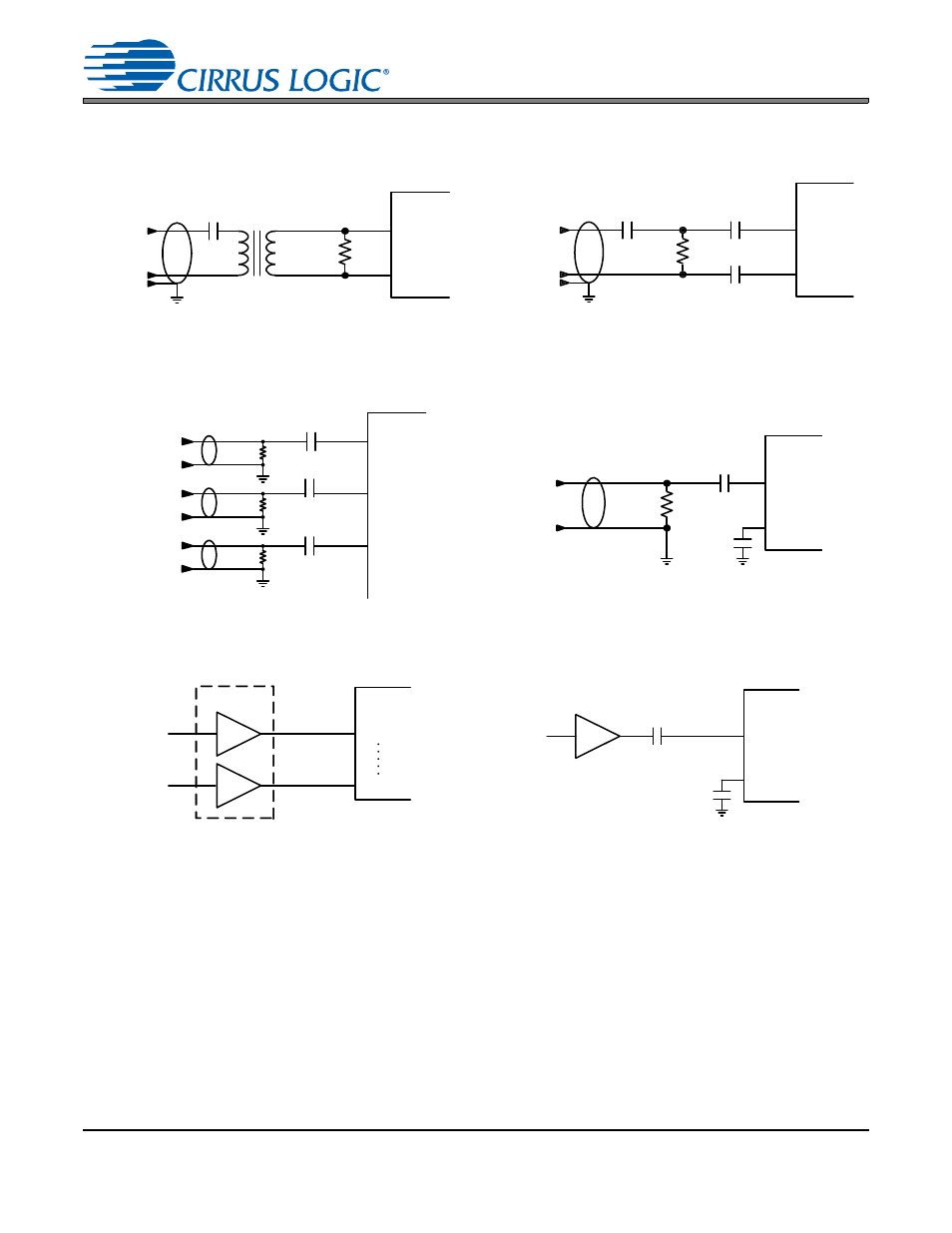
Figure 26. Professional Input Circuit – Differential
Mode
Figure 27. Transformerless Professional Input Cir-
cuit – Differential Mode
RX3
RX0
RX2
75
.01
F
.01
F
.01
F
.
..
75
Coax
75
75
75
Coax
75
Coax
CS8422
RCA Phono
RXP
RXN
CS8422
Coax
75
75
0.01
F
0.01
F
Figure 28. S/PDIF MUX Input Circuit – Single-Ended
Figure 29. Receiver Mode 1 Single-Ended Input
Circuit – Differential Mode
RXP
RXN
CS8422
0.01
F
0.01
F
TTL/CMOS
RX3
CS8422
TTL/CMOS
RX0
Figure 30. S/PDIF MUX Input Circuit – Digital Mode
Figure 31. TTL/CMOS Input Circuit – Differential
Mode