Software register bit definitions, 1 cs8422 i.d. and version register (01h), 2 clock control (02h) – Cirrus Logic CS8422 User Manual
Page 48: Section 11.2
48
DS692F2
CS8422
11.SOFTWARE REGISTER BIT DEFINITIONS
The table row beneath the row that contains the register-bit name shows the register bit default value. Bits labeled
‘Reserved’ must remain at their default value.
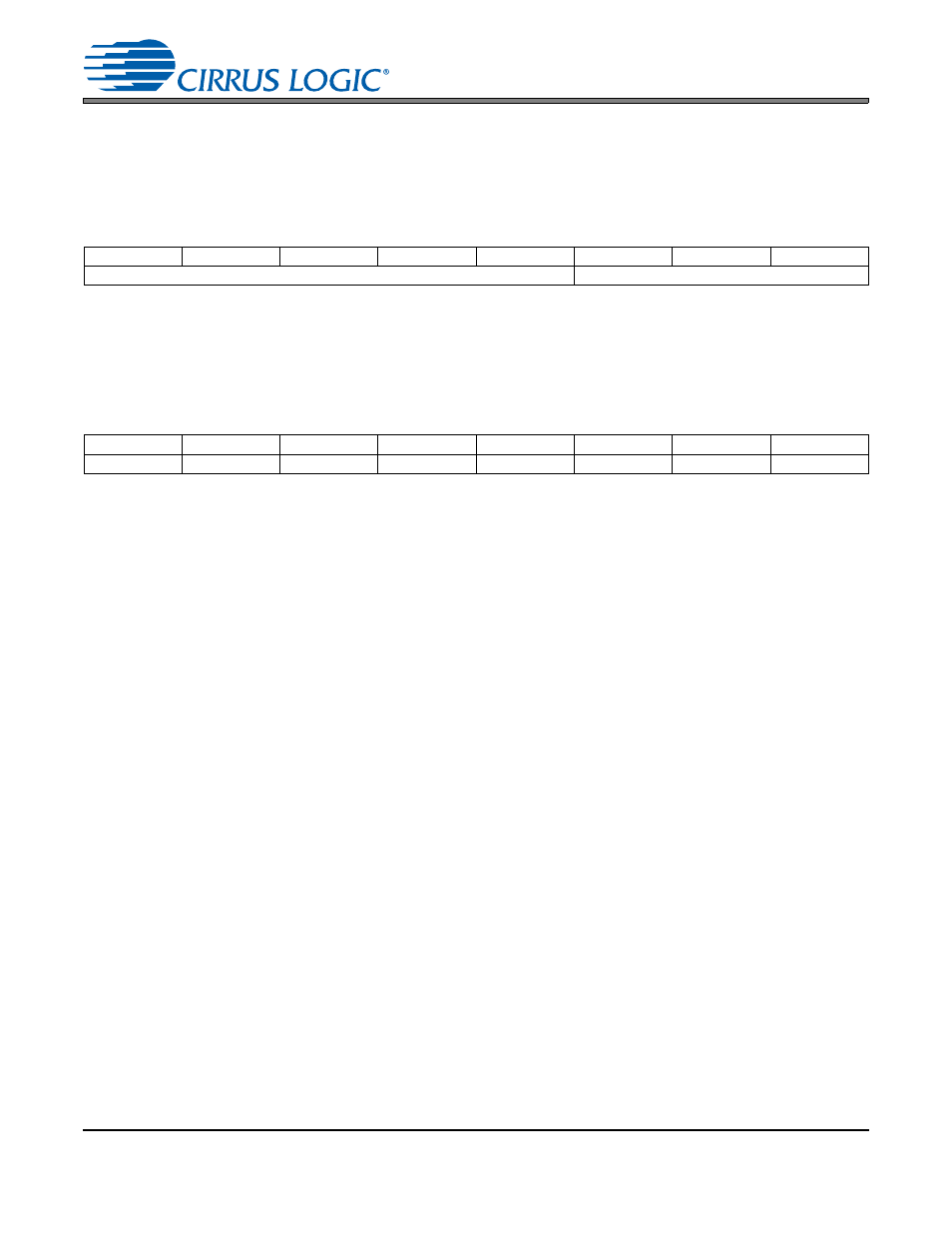
11.1
CS8422 I.D. and Version Register (01h)
ID[4:0] - ID code for the CS8422. Permanently set to 00010
REV[2:0] = 000 (revision A)
REV[2:0] = 010 (revision B1)
11.2
Clock Control (02h)
PDN - Controls the internal clocks, allowing the CS8422 to be placed in a “powered down”, low current con-
sumption state. This bit must be written to the 0 state to allow the CS8422 to begin operation. All input clocks
should be stable in frequency and phase when PDN is set to 0.
0- Normal part operation.
1- Internal clocks are stopped. Internal state machines are reset. The fully static control port is operational,
allowing registers to be read or changed. Power consumption is low.
FSWCLK – Forces the clock signal on XTI to be output on RMCK regardless of the SWCLK bit functionality
or PLL lock.
0 – Clock signal on XTI is output on RMCK according to the SWCLK bit functionality.
1 – Forces the clock signal on XTI to be output on RMCK regardless of the SWCLK bit functionality.
SWCLK - Outputs XTI clock signal on RMCK pin when PLL loses lock. Any OSCLK or OLRCK derived from
RMCK under normal conditions will be derived from XTI in this case.
0 - Disable automatic clock switching.
1 - Enable automatic clock switching on PLL unlock. Clock signal selected on XTI is automatically output
on RMCK on PLL Unlock.
RMCK_CTL[1:0] - RMCK Control
00 - RMCK is an output and is derived from the frame rate of incoming AES3 data.
01 - RMCK is an output and is derived from the ISCLK input frequency divided by 64. Only valid if serial
audio input port is in slave mode (SIMS = 0 in
“Serial Audio Input Data Format (0Bh)” on page 54
).
10 - RMCK is high-impedance.
11 - Reserved
INT[1:0] - Interrupt output pin (INT) control
00 - Active high; high output indicates interrupt condition has occurred.
7
6
5
4
3
2
1
0
ID4
ID3
ID2
ID1
ID0
REV2
REV1
REV0
0
0
0
1
0
0
0
0
7
6
5
4
3
2
1
0
PDN
FSWCLK
SWCLK
RMCK_CTL1 RMCK_CTL0
INT1
INT0
Reserved
1
0
0
0
0
0
0
0