Typical connection diagrams, 1 software mode, Figure 7.typical connection diagram, software mode – Cirrus Logic CS8422 User Manual
Page 22
22
DS692F2
CS8422
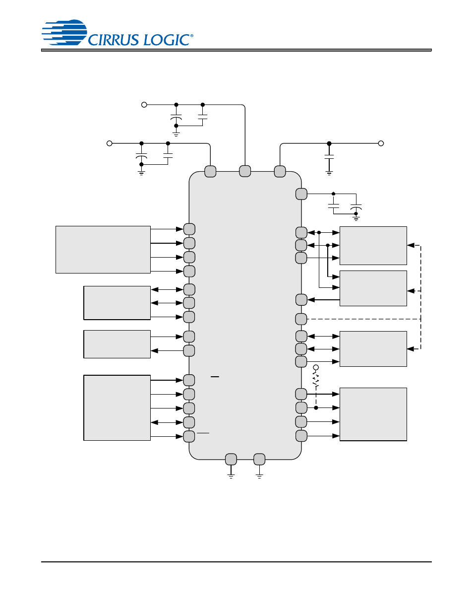
3. TYPICAL CONNECTION DIAGRAMS
3.1
Software Mode
CS8422
VD_FILT
Serial Audio Input
Device
Crystal/Clock Source
Microcontroller
Serial Audio Input
Device
Serial Audio Output
Device
AES3/SPDIF/IEC60958
Receiver Circuitry
Clock Routing,
Interrupt Control,
Channel-Status, and
User Data Output
TDM Output Device
RX0/RXP0
1
RX1/RXN0
2
RX2/RXP1
5
RX3/RXN1
5
ILRCK
13
ISCLK
14
SDIN
15
XTI
11
XTO
12
AD0/CS
7
AD1/CDIN
8
SCL/CCLK
9
SDA/CDOUT
10
RST
32
GPO0 16
GPO1 17
GPO2 18
GPO3 30
D
G
N
D
21
A
GND
4
20
10 µF
0.1 µF
+
RMCK 31
SDOUT2 23
OSCLK2 24
OLRCK2 25
TDM_IN 26
SDOUT1 27
OLRCK1 29
OSCLK1 28
10 µF
0.1 µF
+
V
A
3
+3.3V
V
L
+1.8V to +5V
0.1 µF
22
10 µF
0.1 µF
+
V_R
EG
19
+3.3V
20 k
+VL
Figure 7. Typical Connection Diagram, Software Mode
See
for details.
See also other documents in the category Cirrus Logic Hardware:
- CobraNet (147 pages)
- CS4961xx (54 pages)
- CS150x (8 pages)
- CS1501 (16 pages)
- CS1601 (2 pages)
- CS1601 (16 pages)
- CS1610 (16 pages)
- CRD1610-8W (24 pages)
- CRD1611-8W (25 pages)
- CDB1610-8W (21 pages)
- CS1610A (18 pages)
- CDB1611-8W (21 pages)
- CDB1610A-8W (21 pages)
- CDB1611A-8W (21 pages)
- CRD1610A-8W (24 pages)
- CRD1611A-8W (25 pages)
- CS1615 (16 pages)
- AN403 (15 pages)
- AN401 (14 pages)
- AN400 (15 pages)
- AN375 (27 pages)
- AN376 (9 pages)
- CRD1615-8W (22 pages)
- CRD1616-8W (23 pages)
- AN402 (14 pages)
- AN404 (15 pages)
- CRD1615A-8W (21 pages)
- CS1615A (16 pages)
- CS1630 (56 pages)
- AN374 (35 pages)
- AN368 (80 pages)
- CRD1630-10W (24 pages)
- CRD1631-10W (25 pages)
- CS1680 (16 pages)
- AN405 (13 pages)
- AN379 (31 pages)
- CRD1680-7W (31 pages)
- AN335 (10 pages)
- AN334 (6 pages)
- AN312 (14 pages)
- AN Integrating CobraNet into Audio Products (16 pages)
- CobraNet Audio Routing Primer (9 pages)
- Bundle Assignments in CobraNet Systems (3 pages)
- CS2300-01 (3 pages)
- CS2000-CP (38 pages)