Figure 19.c/u data outputs, Figure 19, Illustrates – Cirrus Logic CS8422 User Manual
Page 36: Note 4), Note 6), Cs8422
36
DS692F2
CS8422
RCBL (out)
VLRCK (out)
C/U (out)
C/U[0]
C/U[1]
C/U[383]
t
t
192 AES3 Frames
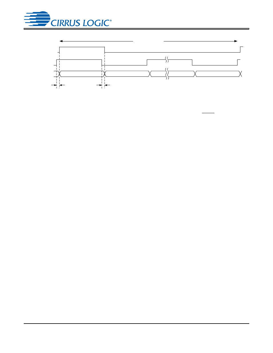
Figure 19. C/U Data Outputs
Note:
1.
RCBL will go high on the transition of the first output C/U data bit (C/U[0]) and will remain high until the C/U[0] - C/U[1] transition.
2.
VLRCK is a virtual word clock that is available through the GPO pins, and can be used to frame the C/U output.
3.
VLRCK frequency is always equal to the incoming frame rate of the AES3-compatible data. If there are an even number of OSCLK
periods per OLRCK, then the VLRCK duty cycle is 50%, otherwise it is 50% ± one OSCLK period.
4.
If a serial audio output port is sourced directly by the AES3-compatible receiver VLRCK = OLRCK in I²S Mode, and
VLRCK = OLRCK in left-justified and Right-Justified Modes.
5.
If a serial port is sourced directly by the AES3-compatible receiver, the data will transition on the fourth OSCLK falling edge after a
VLRCK edge and will be valid on VLRCK edges (t = 4 OSCLK period).
6.
If a serial port is not sourced directly by the AES3-compatible receiver (as in a sample rate conversion application), the data will
transition 1/64*Fsi after a VLRCK edge, and will be valid on VLRCK edges (t = 1/64*Fsi).