1 register definitions, 2 useful %s and %sr registers, Chapter 14: registers – Horner APG XL7 OCS User Manual
Page 74
XL7 User Manual
CHAPTER 14: REGISTERS
14.1 Register Definitions
When programming the XL7 OCS, data is stored in memory that is segmented into different types. This
memory in the controller is referred to as registers. Different groups of registers are defined as either
bits or words (16 bits). Multiple registers can usually be used to handle larger storage requirements.
For example 16 single bit registers can be used to store a Word or two 16 bit registers can be used to
store a 32-bit value.
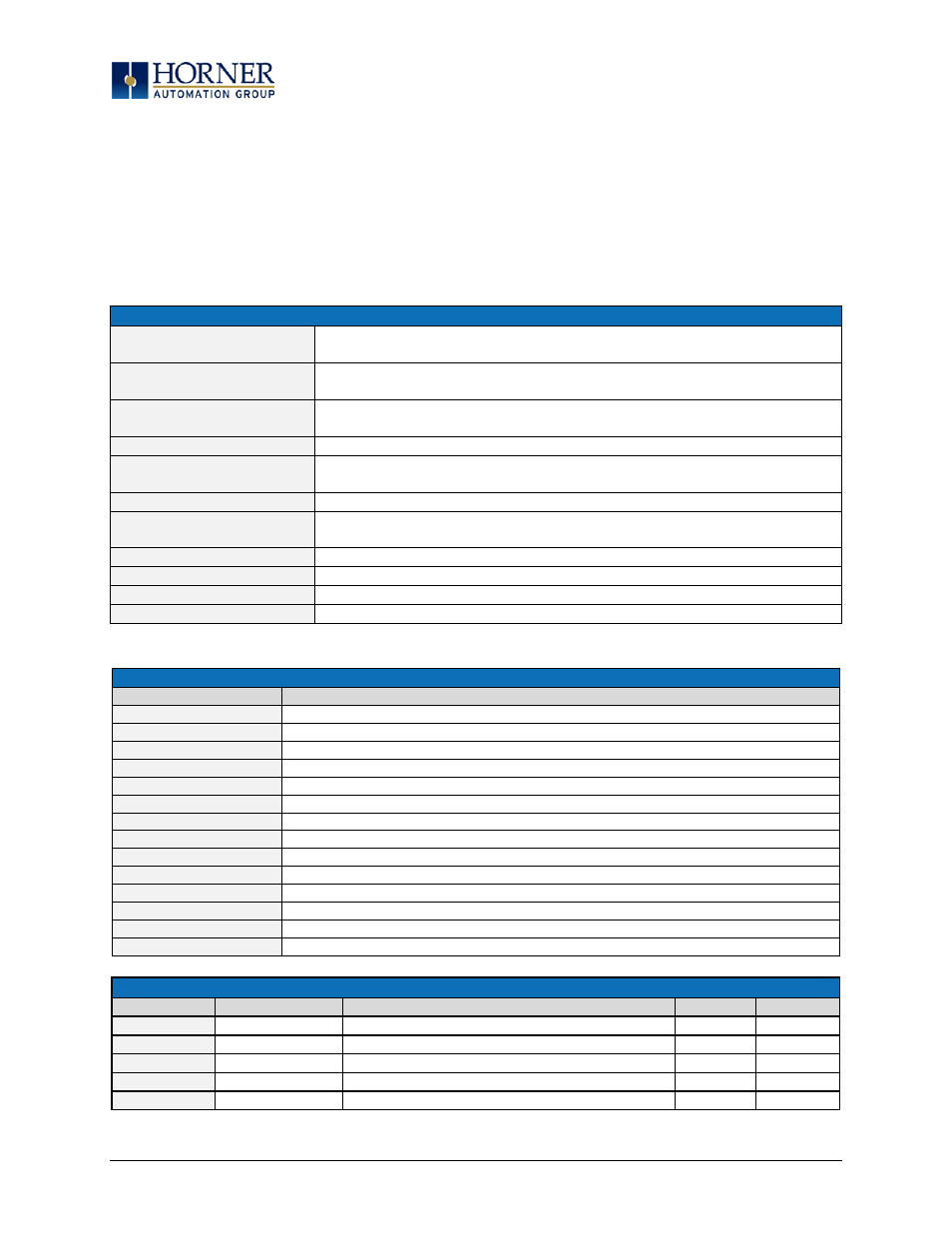
Table 14.1 - Types of Registers found in the XL7 OCS
%AI Analog Input
16-bit input registers used to gather analog input data such as voltages,
temperatures, and speed settings coming from an attached device
%AQ Analog Output
16-bit output registers used to send analog information such a voltages, levels or
speed settings to an attached device
%D Display Bit
These are digital flags used to control the displaying of screens on a unit which has
the ability to display a screen. If the bit is SET, the screen is displayed
%I Digital Input
Single-bit input registers. Typically, an external switch is connected to the registers
%K Key Bit
Single-bit flags used to give the programmer direct access to any front panel keys
appearing on a unit
%M Retentive Bit
Retentive single-bit registers
%Q Digital Output
Single-bit output registers. Typically, these bits are connected to an actuator,
indicator light or other physical outputs
%R General Purpose Register
Retentive 16-bit registers
%S System Bit
Single-bit bit coils predefined for system use
%SR System Register
16-bit registers predefined for system use
%T Temporary Bit
Non-retentive single-bit registers
14.2 Useful %S and %SR registers
Table 14.2 – Common %S Register Definitions
Register
Description
%S1
Indicate First Scan
%S2
Network is OK
%S3
10mS timebase
%S4
100mS timebase
%S5
1 second timebase
%S6
I/O is OK
%S7
Always ON
%S8
Always OFF
%S9
Pause 'n Load soon
%S10
Pause 'n load done
%S11
I/O being forced
%S12
Forcing is enabled
%S13
Network I/O is OK
%S16
Ethernet COM module is OK
Table 14.3 – %SR Registers
Register
Name
Description
Min Val
Max Val
%SR1
USER_SCR
Current User Screen Number
1
1023
%SR2
ALRM_SCR
Current Alarm Screen Number (0=none)
0
1023
%SR3
SYS_SCR
Current System Screen Number (0=none)
0
14
%SR4
SELF_TEST
Bit-Mapped Self-Test Result
0
65535
%SR5
CS_MODE
Control Station Mode (0=Idle, 1=Do I/O, 2=Run)
0
2
Page 74 of 110