Chapter 6: can communications, 1 overview, 2 port description – Horner APG XL7 OCS User Manual
Page 26
XL7 User Manual
CHAPTER 6: CAN COMMUNICATIONS
Note: For additional CAN information, refer to the CAN Networks manual (MAN0799) on the Horner
websites.
6.1
Overview
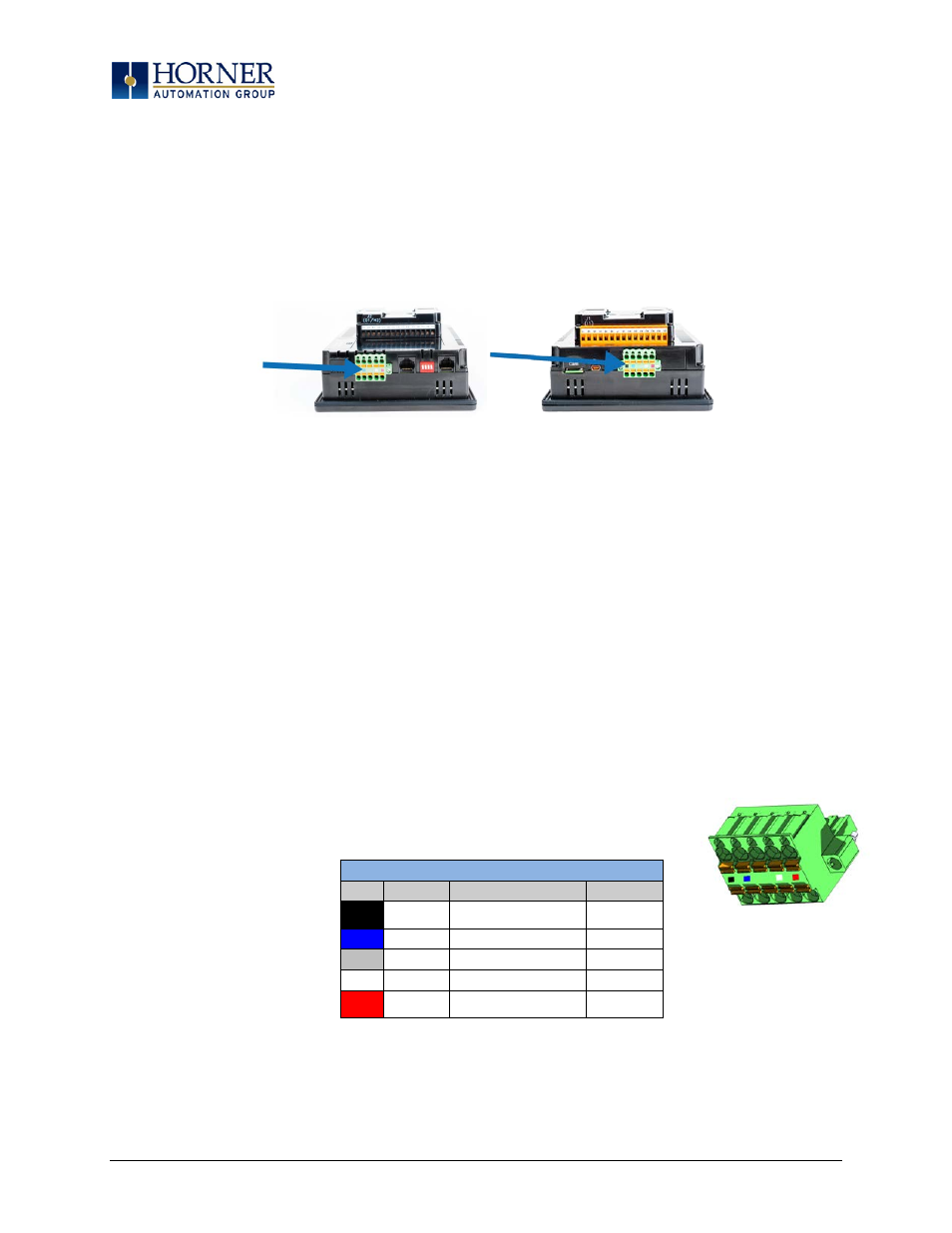
All XL7 OCS models provide two CAN network ports, which are implemented with 5-pin connectors.
The connectors are labeled CAN1 and CAN2.
Figure 6.1 – CAN1 & CAN2 Connector Locations
Like the MJ1 serial port, the CAN1 port can be used for XL7 OCS programming by connecting it to the
CAN port of a PC running Cscape. The CAN1 port also allows the XL7 OCS to exchange global data with
other OCS/RCS controllers. Both CAN1 and CAN2 support accessing of remote network I/O devices
(SmartStix, SmartBlock and SmartRail Modules.)
CAN2 port supports CsCAN, CANopen, J1939 and DeviceNet Master (layer 3 as a selectable option – one
only)
6.2
Port Description
The XL7 OCS CAN ports implement the ISO 11898-2 physical layer and the CAN 2.0A data link layer
standards. Also, since the CAN ports are powered by an internal isolated power supply, external CAN
power is not required.
6.3
CAN Port Wiring
Figure 6.2 – CAN1 / CAN2 Port Pins
CAN1 & CAN2 Port Pins
Pin
Signal
Signal Description
Direction
1
V-
CAN and Device Ground -
Black
−
2
CN_L
CAN Data Low - Blue
In/Out
3
SHLD
Shield Ground - None
−
4
CN_H
CAN Data High - White
In/Out
5
V+
Positive DC Voltage Input
(10-30VDC) - Red
−
CAN Connector
Use the CAN Connector when
using CsCAN or other CAN
network.
Torque rating 4.5 – 7 Lb-In
(0.50 – 0.78 N-m)
CAN1
CAN2
Page 26 of 110