Horner APG XL7 OCS User Manual
Page 54
XL7 User Manual
12.3 System Menu – Details
The following sections describe each of the Sub-Menus in detail.
Set Networks
This sub menu allows setting for the CAN and Ethernet network to be viewed or changed.
CAN Ok?
Yes= CAN1 connected to a CAN network and functioning properly
No= Not ready to communicate on CAN network
CAN ID
1 to 253 = This node’s CsCAN Network ID; must be unique on network
CAN Baud
125 KB = 125 KBaud CAN network
250 KB = 250 KBaud CAN network
500 KB = 500 KBaud CAN network
1 MB = 1 MBaud CAN network
MAC ID
Displays the Ethernet MAC ID of the unit
IP
Displays the Ethernet IP address of the unit
NetM
Displays the Ethernet net mask of the unit
GatWy
Displays the Ethernet gateway of the unit
NOTE: The IP address, Net Mask and Gateway can be changed from the system menu. This is designed
for commissioning or temporary field changes. The actual parameters are defined in Cscape under the
Ethernet configuration and are reverted to whenever the unit goes from idle to run mode.
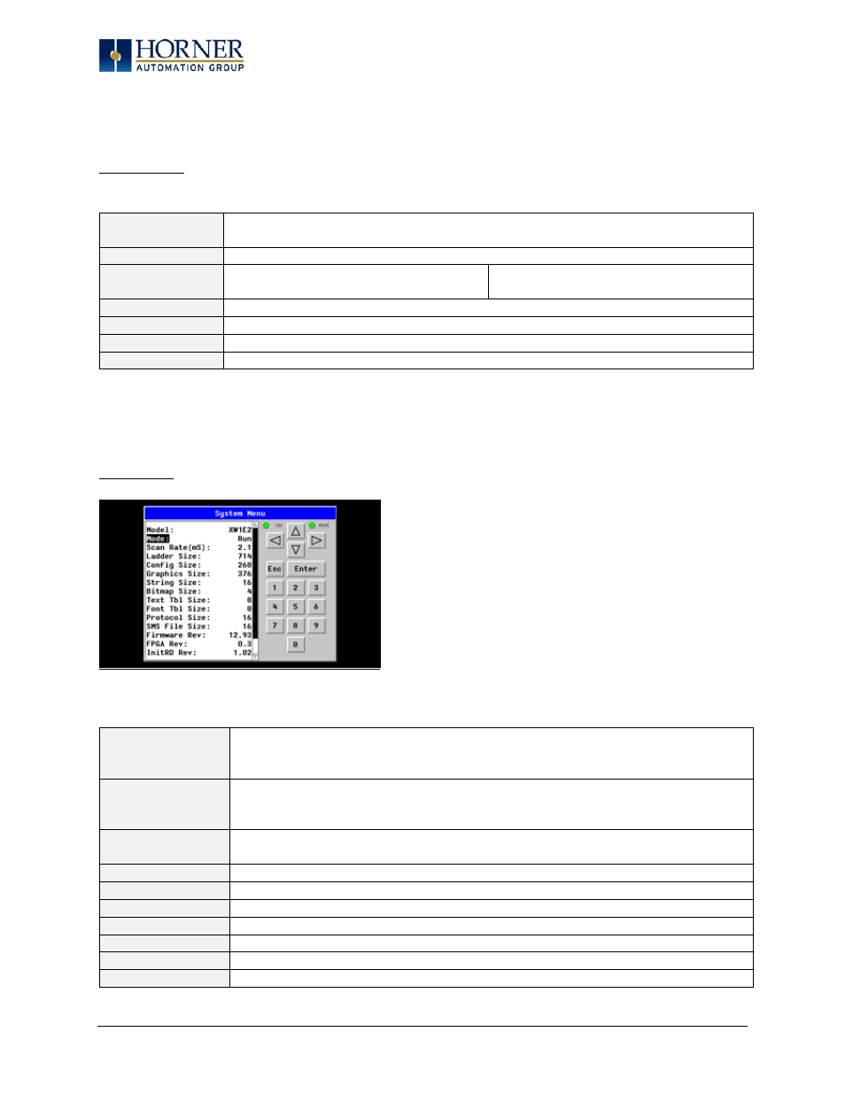
View Status
The View Status Sub-Menu displays up to 19 System Settings. Only the OCS Mode System Setting is editable.
Model
XW1yz= Model number of this XL7 OCS unit
1yz = indicates the installed I/O module
00 = no I/O module
OCS Mode
Idle = XL7 OCS is in Idle mode
DoIO = XL7 OCS is in Do I/O mode
Run = XL7 OCS is in Run mode
Scan Rate(mS)
0.0 = XL7 OCS is not in Run mode
0.1 to 999.9= Average number of mS for each ladder scan
OCS Net Use %
0.0 to 100.0 = CAN network bandwidth % used by this XL7 OCS node
All Net Use %
0.0 to 100.0 = CAN network bandwidth % used by all nodes
Ladder Size
x = Number of bytes in application ladder program
Config Size
x = Number of bytes in application I/O configuration
Graphics Size
x = Number of bytes in application graphic screens
String Size
x = Number of bytes in application string table
Bitmap Size
x = Number of bytes in application bitmaps
Page 54 of 110