3 model and i/o overview – Horner APG XL7 OCS User Manual
Page 40
XL7 User Manual
10.3 Model and I/O Overview
Table 10.1 – I/O and Model Overview
XL7 Models
DC In
DC Out
Relays
HS In
HS Out
mA/V In
mA/V RTD/Tc
mA/V Out
HE-XW1E0 /
HEXT391C100
HE-XW1E2 /
HEXT391C112
12
6
4
4
HE-XW1E3 /
HEXT391C113
12
12
4
2
2
HE-XW1E4 /
HEXT391C114
24
16
4
2
2
HE-XW1E5 /
HEXT391C115
12
12
4
2
2
2
Table 10.1 shows the different types of I/O included with the various XL7 OCS models. Specific specifications,
jumper settings and wiring diagrams can be found on the data sheets attached at the end of the manual.
Descriptions and applications of the different type of I/O can be found below.
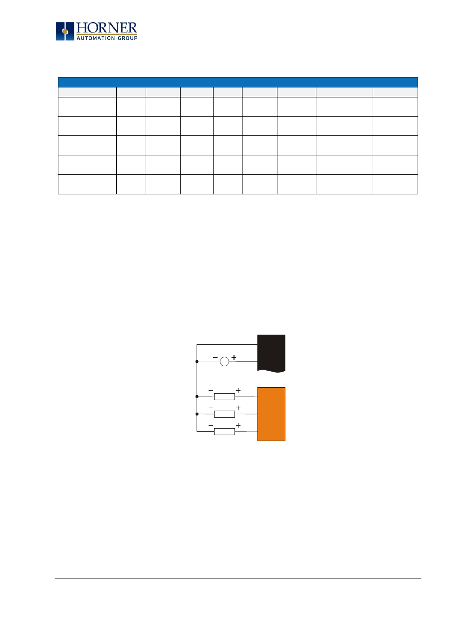
10.4 Solid-State Digital Outputs
Solid-state digital outputs are generally used to activate lamps, low voltage solenoids, relays and other low
voltage and low current devices.
NOTE: The digital outputs used on the XL7 OCS are “sourcing” outputs. This means the output applies a
positive voltage to the output pin when turned ON. When turned off, the output applies approximately zero
volts with respect to the I/O ground.
Figure 10.4 – Typical Output Wiring
The digital outputs used in the XL7 OCS have electronic short circuit protection and current limiting. While
these electronic protections work in most applications, some application may require external fusing on
these outputs.
The digital outputs in the XL7 OCS are typically controlled via %Q bits in the register mapping. Some of the
outputs are designed for high-speed applications and can be used for PWM or frequency output
applications. Please see the data sheet and the chapter on High Speed I/O for additional information.
Q14
Q15
V+
0V
LOAD
LOAD
10 - 30VDC
Q16
LOAD
J2
J4
Page 40 of 110