6 pwm functions register map – Horner APG XL7 OCS User Manual
Page 51
XL7 User Manual
NOTE: Setting the PLC mode to stop while the stepper is in operation causes the stepper output to
immediately drop to zero and the current stepper count to be lost.
NOTE: The stepper output level may cause damage or be incompatible with some motor drive inputs.
Consult drive documentation to determine if output level and type is compatible.
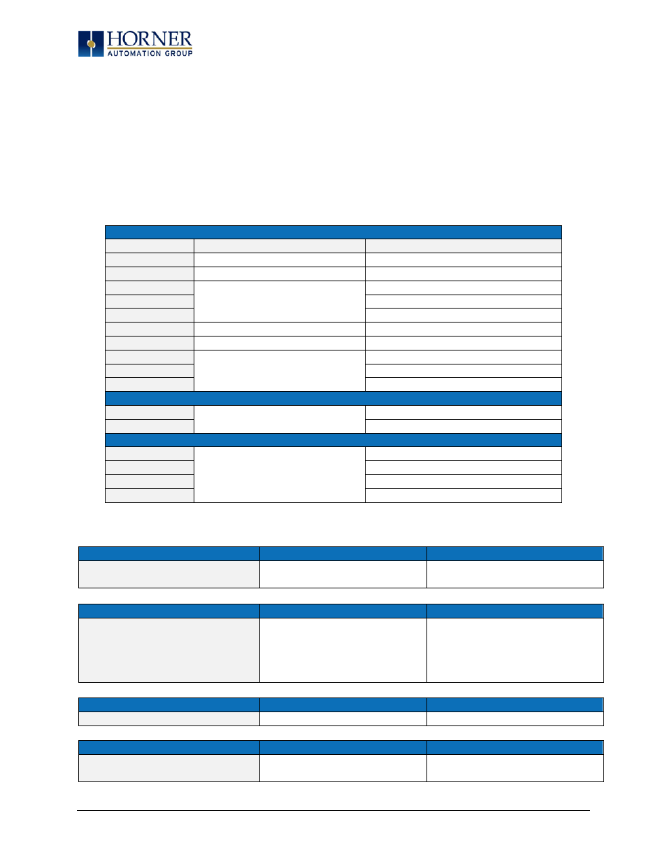
11.6 PWM Functions Register Map
The register assignments for the high speed I/O can be moved via a setting in Cscape. The values shown
are the DEFAULT values and may not match the same starting point as the values shown below.
Table 11.3 – PWM Functions Register Map
Register
PWM
Stepper
%AQ421-422
PWM 1 Duty Cycle (32-bit)
Start Frequency – Stepper 1
%AQ423-424
PWM 1 Frequency
Run Frequency – Stepper 1
%AQ425-426
Acceleration Count – Stepper 1
%AQ427-428
Run Count – Stepper 1
%AQ429-430
Deceleration Count – Stepper 1
%AQ431-432
PWM 2 Duty Cycle (32-bit)
Start Frequency – Stepper 2
%AQ433-434
PWM 2 Frequency
Run Frequency – Stepper 2
%AQ435-436
Acceleration Count – Stepper 2
%AQ437-438
Run Count – Stepper 2
%AQ439-440
Deceleration Count – Stepper 2
%Q1
Digital Out – Stepper 1
%Q2
Digital Out – Stepper 2
%I1617
Ready/Done – Stepper 1
%I618
Error – Stepper 1
%I1619
Ready/Done – Stepper 2
%I620
Error – Stepper 2
11.7 PWM Examples
Example 1
Duty Cycle
Frequency
To get a 50% Duty Cycle @ 10 kHz
waveform on PWM1:
Set %AQ421-422 = 16,000
Set %AQ423-424 = 10,000
Example 2
Duty Cycle
Frequency
To get a 50% Duty Cycle on PW1 and
90 % Duty Cycle on PWM2 @ 1 kHz
waveform:
Set %AQ421-422 = 16,000
Set %AQ431-432 = 28,800
(duty cycle (32000 * 0.9))
Set %AQ423-424 = 1,000
Set %AQ433-434 = 1,000
Example 3
Duty Cycle
Frequency
To turn PWM 1 output ON all the time
Set %AQ421-422 = 32,000
Set %AQ423-424 = Any Value
Example 4
Duty Cycle
Frequency
To turn PWM 1 output OFF all the
time
Set %AQ421-422 = 0
Set %AQ423-424 = Any Value
Page 51 of 110