6 digital inputs, 7 analog inputs – Horner APG XL7 OCS User Manual
Page 42
XL7 User Manual
Protection for Inductive Loads
Inductive loads can cause reverse currents when they shut off that can shorten the life of relay contacts.
Some protective measures need to be determined by an engineer. If you have questions on protection from
inductive load, consult an application engineer or HEAPG Technical Support. Details on devices that may
protect outputs can be found in MAN0962-01.
Output State on Controller Stop
When the controller is stopped the operation of each output is configurable. The outputs can hold the
state they were in before the controller stopped or they can go to a predetermined state. By default
relay outputs turn off. For more information on stop state see the
10.6 Digital Inputs
NOTE: Refer to the datasheet for XL7 OCS model being used for details on jumper settings.
Note: The digital inputs on the XL7 OCS are designed for low voltage DC inputs. The inputs are designed
to support both positive and negative input modes. The mode is set by a jumper setting and a
configuration parameter in Cscape. All the inputs on the unit must be configured to the same mode.
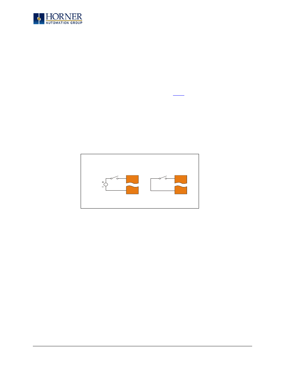
Figure 10.6 – Positive and Negative Inputs
In positive logic mode a positive voltage applied to the input will turn the input. The internal design of
this mode is basically a resistor from the input to I/O ground. This mode is sometimes called sourcing.
In negative logic mode, connecting the input to the I/O ground or zero volts will turn the input on. The
internal design of this mode is basically a resistor from the input to the positive I/O voltage (usually 12
or 24 volts). This mode is sometime called sinking.
Some of the digital inputs may support high speed input functional such as counting or frequency
measurement.
10.7 Analog Inputs
NOTE: See the data sheet for the XL7 OCS model being used for jumper settings and see the appropriate page
in this manual (see Index) for details on how to use Cscape to configure the digital filtering.
The analog inputs on the XL7 OCS allow voltage or current measurement from a variety of devices. The
voltage or current mode is set though jumpers on the unit and settings in Cscape. Each channel can be
separately configured for voltage or current mode.
I1
0V
001XLE036
12-24VDC
I1
0V
Positive Logic In Negative Logic In
Positive Logic vs. Negative Logic Wiring
The XL SERIES OCS can be wired for Positive Logic inputs or
Negative Logic inputs.
Page 42 of 110