Horner APG XL7 OCS User Manual
Page 39
XL7 User Manual
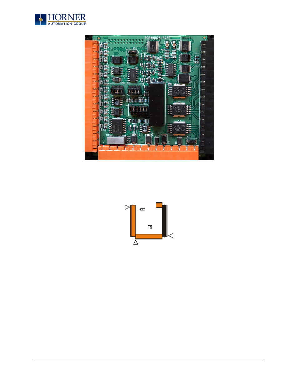
Figure 10.2 – XL7 I/O Cover Removed (sample I/O board)
Once the back is removed the jumper selection can be changed. The jumper settings are documented
on each data sheet using a diagram such as Figure 9.4 below and a description of the jumper settings.
Figure 10.3 – Example Jumper Diagram
To re-install the cover, place the I/O cover back on the unit.
Place the screw back into the hole and turn the screw slowly counter clockwise until it clicks into the
threads. This prevents the screw from being cross-threaded. Now turn the screw clock-wise until the
cover is firmly secured. Repeat this process for all four (4) screws.
Ensure not to exceed the recommended
max torque of 7-10 lb-in. [0.8 – 1.13 Nm.]
J1
J2
J3
JP3
JP1
001XLE005-R1
J4
Page 39 of 110
- XLe OCS HE-XE100 (3 pages)
- XLe OCS HE-XE102 (4 pages)
- XLe OCS HE-XE102-10 (4 pages)
- XLe OCS HE-XE102-14 (4 pages)
- XLe OCS HE-XE102-62 (4 pages)
- XLe OCS HE-XE103 (4 pages)
- XLe OCS HE-XE103-10 (4 pages)
- XLe OCS HE-XE105 (4 pages)
- XLe OCS (100 pages)
- XLt OCS HE-XT100 (3 pages)
- XLt OCS HE-XT102-10 (4 pages)
- XLt OCS HE-XT102-14 (4 pages)
- XLt OCS HE-XT102 (4 pages)
- XLt OCS HE-XT103-10 (4 pages)
- XLt OCS HE-XT103 (4 pages)
- XLt OCS HE-XT105 (4 pages)
- XL4 OCS HE800ETN200 (98 pages)
- XL4 OCS (6 pages)
- XL4 OCS (122 pages)
- XL6 OCS HE-XL102 (6 pages)
- XL6 OCS HE-XL102 (4 pages)
- XL6 OCS HE-XL1014 (7 pages)
- XL6 OCS HE-XL103 (6 pages)
- XL6 OCS HE-XL105 (8 pages)
- XL6 OCS (135 pages)
- XL7 OCS (7 pages)
- XL10e OCS Built-in I/O Model 3 (3 pages)
- XL10e OCS Built-in I/O Model 5 I/O (4 pages)
- XL10e OCS Built-in I/O Model 2 I/O (3 pages)
- XL10e OCS (4 pages)
- QX351 OCS HE-QX351 (5 pages)
- QX351 OCS HQX351 (109 pages)
- QX451 OCS (16 pages)
- QX451 OCS (12 pages)
- QX451 OCS (7 pages)
- QX551 OCS (1 page)
- QX451 OCS (95 pages)
- QX501 OCS HE-QX501 (3 pages)
- QX751 OCS (6 pages)
- QX751 OCS (96 pages)
- ZX 1152 OCS HE-ZX452 (6 pages)
- RX371 OCS HE-RX371 (5 pages)
- RX371 OCS HRX371 (124 pages)
- RCC HE-RCC972 (4 pages)