Chapter 10: general i/o, 1 overview, 2 removing the xl7 ocs i/o cover – Horner APG XL7 OCS User Manual
Page 38
XL7 User Manual
CHAPTER 10: GENERAL I/O
Note: Each XL7 OCS unit is sent with a datasheet in the box. The datasheet is the first document to
refer to for model-specific information related to XL7 OCS models such as pin-outs, jumper settings,
and other key installation information. Visit the Horner websites to obtain datasheets, user
documentation, and updates.
10.1 Overview
The XL7 OCS is a compact unit that contains high density, very versatile I/O. Using the I/O properly
requires wiring to the proper terminals, configuring jumpers inside the XL7 OCS unit and configuring
Cscape properly. This section will offer some tips and suggestions to configure the I/O properly. For the
register mapping of the I/O, refer to the
at the end of this manual for the pages referencing
register mapping.
10.2 Removing the XL7 OCS I/O Cover
Some I/O configurations require jumper settings to be changed in the XL7 OCS unit. Examples of these
settings are setting positive or negative logic on digital inputs or setting current or voltage on analog
inputs.
Each XL7 OCS I/O jumper is set to a factory default. Refer to the XL7 datasheet to find the default
setting to determine if a jumper change is necessary for a particular application.
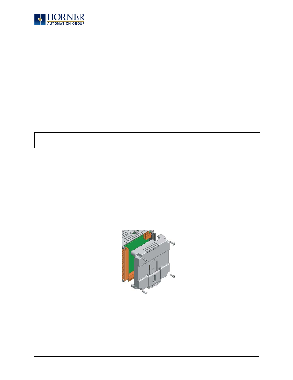
To remove the I/O cover of the XL7 OCS, remove the four (4) Phillips screws from the I/O back. It may
help to place the XL7 OCS unit face down on a clean work surface. Once the four screws are removed
the I/O cover can be lifted straight off.
Figure 10.1 – Removing the I/O Cover
WARNING: Power, including I/O power must be removed from the unit prior to removing the
back cover. Failure to do so could result in electrocution and/or damage to equipment
Page 38 of 110