1 normal, 2 pwm – Horner APG XL7 OCS User Manual
Page 49
XL7 User Manual
11.5.1 Normal
When either Q1 or Q2 is configured for Normal operation, the digital output registers %Q1 and %Q2 drives
that respective output.
11.5.2 PWM
When either Q1 or Q2 is configured for PWM, the PWM function drives that respective output. Both PWM
channels may be individually enabled and can have independent frequency and duty cycles.
The PWMs require two parameters (%AQs) to be set for operation. These parameters may be set at run-
time.
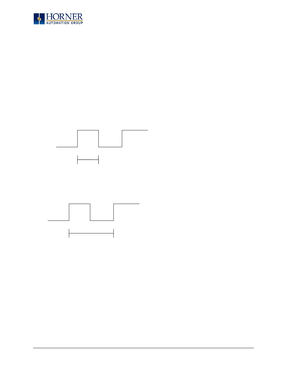
Duty Cycle - The Duty Cycle is a 32 bit value from 0 to 32,000 indicating the relative duty cycle of the
output. For example a value of 8000 would indicate a 25% duty cycle, a value of 16,000 would indicate a
50% duty cycle. 0 turns the output off, 32,000 turns the output on.
Frequency - The Frequency is a 32 bit value indicating the output frequency in Hertz. One over the
frequency is the period.
Figures 11.6 & 11.7 – PWM, two parameters, Duty Cycle & Frequency
At controller power-up or during a download, the PWM output is maintained at zero until both the
Frequency and the Duty cycle are loaded with non-zero values. When the controller is placed in stop mode,
the state of the PWM outputs is dependent on the PWM State on Controller Stop configuration. This
configuration allows for either hold-last-state or specific frequency and duty cycle counts. Specifying zero
for either the period or duty causes the PWM output to remain low during stop mode.
NOTE: for standard I/O modules (1E3, 1E4 and 1E5 models,) the nominal output driver turn-on-time delay
(to reach 50% output) is 25 microseconds. Therefore, this limitation should be considered when
determining both the minimum pulse width and the duty cycle accuracy of the application. Special high
speed output options will be available.
Period
Duty Cycle
Page 49 of 110