Sig nal wiring 13, User in put wiring 13, Ac power wiring 13 – Red Lion TSC User Manual
Page 15
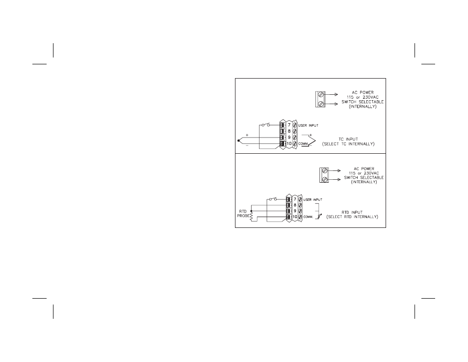
Signal Wiring
When connecting the thermocouple or RTD leads, be certain that the
connections are clean and tight. If the thermocouple probe cannot be
connected directly to the controller, thermocouple wire or thermocouple
extension-grade wire must be used to extend the connection points (copper
wire will not work). Always refer to the thermocouple manufacturer’s
recommendations for mounting, temperature range, shielding, etc. For
multi-probe temperature averaging applications, two or more thermocouple
probes may be connected to the controller (always use the same type).
Paralleling a single thermocouple to more than one controller is NOT
recommended. Generally, the red wire from the thermocouple is negative and
connected to the controller’s common.
RTD sensors are used where a higher degree of accuracy and stability is
required when compared to thermocouples. Most RTD sensors available are
the three wire type. The third wire is a sense lead for canceling the effects of
lead resistance of the probe. Four wire RTD elements may be used by leaving
one of the sense leads disconnected.
Two wire RTD sensors may be used in either of two ways:
A) Install a shorting wire between terminals #8 & #9. A temperature offset
error of 2.5°C/ohm of lead resistance will exist. The error may be
compensated for by programming a temperature offset.
B) Install a copper sense wire of the same wire gage as the RTD leads. Attach
one end of the wire at the probe and the other end to terminal #8. Complete
lead wire compensation will be in effect. (preferred method)
Note: With extended cable runs, be sure the lead resistance is less than 10
ohms/lead.
User Input Wiring
The programmed User Input function is performed when terminal #7 is
used in conjunction with common (terminal #10). Any form of mechanical
switch may be connected to terminal #7. Sinking open collector logic with less
than 0.7 V saturation may also be used (no pull-up resistance is necessary).
Note: Do not tie the commons of multiple units to a single switch. Use either a
multiple pole switch for ganged operation or a single switch for each unit.
AC Power Wiring
Primary AC power is connected to the separate two position terminal block
labeled AC. To reduce the chance of noise spikes entering the AC line and
affecting the controller, a separate AC feed should be used to power the
controller. Be certain that the AC power to the controller is relatively “clean”
and within the -15%, +10% variation limit. Connecting power from heavily
loaded circuits or circuits that also power loads that cycle on and off, (contacts,
relays, motors, etc.) should be avoided.
-13-
Thermocouple Connection
RTD Connection