Figure 2, Inside the transmitter – Vaisala PTU300 User Manual
Page 27
Chapter 2 ___________________________________________________________ Product Overview
VAISALA ________________________________________________________________________ 25
0604-060
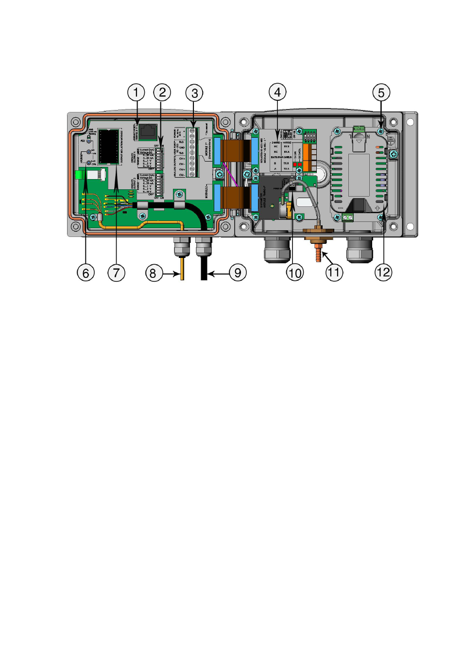
Figure 2
Inside the Transmitter
The following numbers refer to Figure 2 above:
1
=
Service port (RS-232)
2
=
DIP switches for analog output settings
3
=
Power supply and signal wiring screw terminals
4
=
Relay, RS-422/485, data logger, LAN, WLAN, or analog
output module (optional)
5
=
Grounding connector for power supply module
6
=
Adjustment buttons (chemical purge buttons) with indicator
LED
7
=
Galvanic isolation module (optional)
8
=
Temperature probe cable
9
=
Humidity probe cable
10 =
BARO-1 module
11 =
Pressure port
12 =
Power supply module.
See also other documents in the category Vaisala Tools:
- DM500 (138 pages)
- DM70 (93 pages)
- DMT132 (74 pages)
- DMT143 (76 pages)
- DMT152 (70 pages)
- DMT242 (4 pages)
- DMT340 (191 pages)
- DMT345 (185 pages)
- DPT145 (63 pages)
- DPT146 (71 pages)
- PTB330TS (89 pages)
- PTB220 (113 pages)
- PTB220 (10 pages)
- PTB330 (144 pages)
- PTU200 (64 pages)
- PTU200MIK1 (18 pages)
- SPH10 (2 pages)
- SPH20 (2 pages)
- PTB110 (4 pages)
- PTB200 (30 pages)
- PTB210 (analog) (27 pages)
- PTB210 (serial) (32 pages)
- GM70 (68 pages)
- GMD20 (4 pages)
- GMK220 (18 pages)
- GML20 (2 pages)
- GML20T (2 pages)
- GMM20W (5 pages)
- GMM220 (6 pages)
- GMP231 (2 pages)
- GMP231 (90 pages)
- GMP343 (94 pages)
- GMR20 (2 pages)
- GMT220 (42 pages)
- GMW90 (101 pages)
- XMW90 (4 pages)
- MM70 (67 pages)
- MM70 (71 pages)
- MMT162 (66 pages)
- MMT310 (81 pages)
- MMT330 (181 pages)
- MMT330 (171 pages)