Vaisala PTB110 User Manual
Vaisala barocap, Barometer ptb110 series, User's guide
www.vaisala.com
M210839EN-A
1
USER'S GUIDE
Vaisala BAROCAP
®
Barometer PTB110 Series
–
Several pressure ranges
–
Accuracy ±0.3 hPa at +20 °C
–
Long-term stability ±0.1 hPa/year
–
On/off control with external trigger
–
Output voltage 0 … 2.5 or 0 … 5 VDC,
frequency output
–
Current consumption less than 4 mA
–
Mountable on a (35 mm wide) DIN rail
–
NIST traceable (certificate included)
–
BAROCAP
®
sensor
PRODUCT DESCRIPTION
The PTB110 barometer is a micro controller based barometer
including a voltage or frequency output. The barometer can be
supplied with several pressure ranges. The output of the
barometer is a calibrated barometric pressure reading.
The barometer uses the Vaisala BAROCAP
®
Sensor, a silicon
capacitive sensor developed by Vaisala for barometric pressure
measurement applications. The BAROCAP
®
sensor is especially
designed for accurate and stable measurement of barometric
pressure.
INSTALLATION
The PTB110 barometer is intended to be installed indoors.
Installing outdoors requires a protecting enclosure. A DIN rail
mounting option enables the mounting of the barometer on a 35
mm wide standard DIN mounting rail.
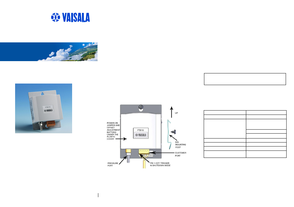
The barometer should be installed in a vertical position with the
connectors pointing downwards to prevent accumulation of
condensated water
.
OPERATING MODES
The PTB110 barometer has two operating modes, the normal
and the shutdown mode. The factory setting is the normal mode
.
Normal Mode
The device is in the normal mode when the power on
jumper is connected (see figure on the following page).
In the normal mode the barometer measures
continuously when powered-up.
Shutdown Mode
The device is in the shutdown mode when the power
on jumper is not connected.
In the shutdown mode, the barometer can be turned on
or off by switching the pin 1. The pin 1 is located at
the customer port, on the left edge of the screw
terminal.
NOTE
The other jumpers inside the barometer are
set at the factory and they must not be
touched.
ELECTRICAL CONNECTIONS
The PTB110 barometer contains a screw terminal block located at
the customer port. The screw terminal includes the electrical
input/output pins presented in the table below.
Pins in screw terminal
Description/Value
Pin 1: EXT_TRIG
External trigger input
Pin 1 is used as a power on/off
switch in shutdown mode as
follows:
Power off
0 VDC
Power on
5 VDC
Pin 2: AGND
Analog ground
Pin 3: GND
Ground
Pin 4: SUPPLY
Supply voltage
Pin 5: VOUT/FOUT
Voltage output/
Frequency output
In the normal mode no connection to the Pin 1 EXT_TRIG is
recommended.
The barometer is protected against a reverse operating voltage.
Both grounds (AGND and GND) are in the same electrical
potential in the barometer. Both three-wire and four-wire
connections can be used. However, it is recommended to use the
four-wire connection, especially if the signal wires are long.