Enabling/disabling relays, Setting relay outputs, Figure 62 – Vaisala PTU300 User Manual
Page 139: Relay indicators on display
Chapter 4 _________________________________________________________________ Operation
VAISALA _______________________________________________________________________ 137
Enabling/Disabling Relays
You can deactivate the relay outputs for example for service purposes of
your system.
Setting Relay Outputs
NOTE
When you have only one relay module installed, its relays are called
“relay 1” and “relay 2”.
When you have two relay modules, the relays of the module connected
to slot MODULE 1 are called “relay 1” and “relay 2” and relays
connected to slot MODULE 2 are called “relay 3” and “relay 4”.
0706-055
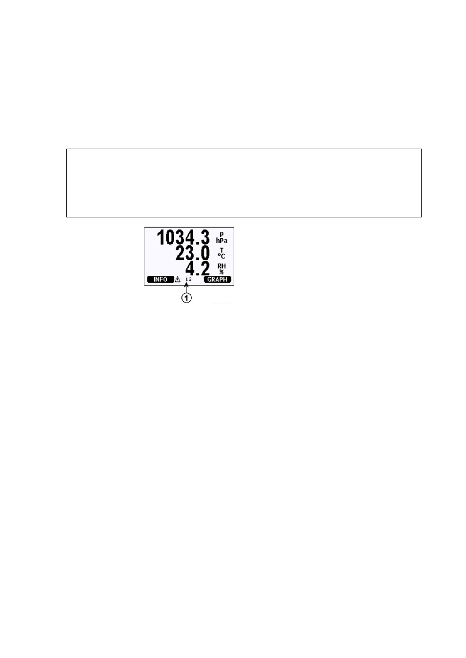
Figure 62
Relay Indicators on Display
Number refers to Figure 62 above:
1
= Lists enabled relays. Activation state shown in black. Disabled
relays are not shown.
Use the display/keypad to set the relay outputs.
1.
Press any of the arrow buttons to open the Main Menu.
2.
Select Interfaces and press the right arrow button.
3.
Select Relay outputs and press the right arrow button.
4.
Select Relay 1/2/3/4, press the right arrow button.
5.
Select Quantity, press the CHANGE button. Select quantity by
using the up/down arrow buttons. Confirm your selection by
pressing the SELECT button.
6.
Select Act. above/Act. below. Press the SET button. You may be
asked, whether you want to modify the value or remove the
setpoint. In this case, select MODIFY to adjust the value or
REMOVE to clear the setpoint. Adjust numeric values by pressing
the up/down/left/right arrow buttons. Confirm your selection by
pressing the OK button.
7.
Select Hysteresis. Press the SET key and adjust the value. Finally
press the OK button.