Starting the mpx100/100b, 10 the mpx100 port and led locations, Start the mpx100/100b – HP EVA Array iSCSI Connectivity Option User Manual
Page 45
Starting the mpx100/100b
To start the mpx100/100b:
1.
Attach the AC power cord to the mpx100/100b and the power distribution unit (PDU). Verify
that the mpx100’s/100b's System Power LED is illuminated.
The mpx100/100b runs a self-test and begins normal operation.
2.
Verify that the Heartbeat LED is blinking (once per second) and that the Input Fault LED is not
illuminated.
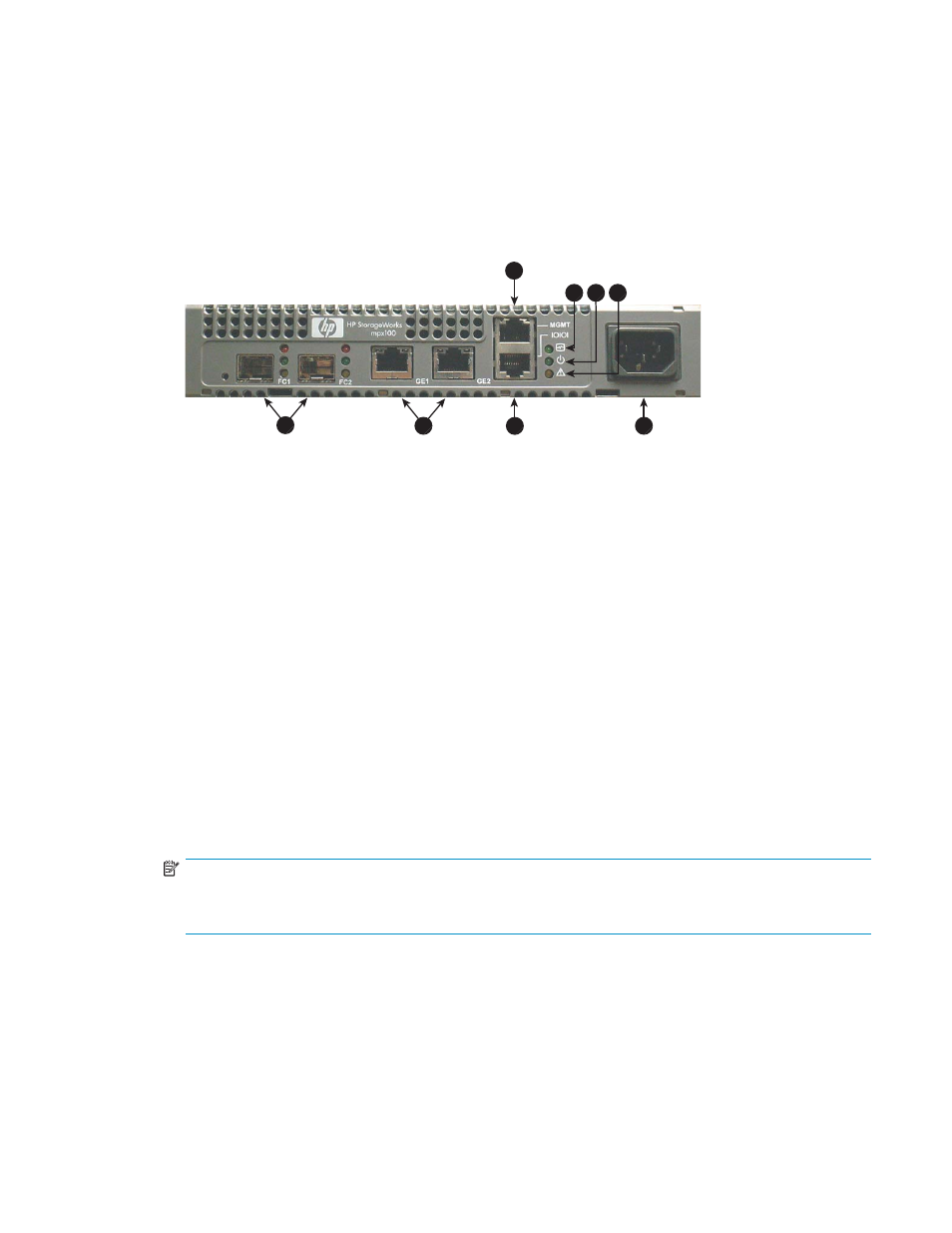
shows the location of the ports and LEDs on the mpx100/100b.
25087a
8
5
6
7
2
3
4
1
Figure 10 The mpx100 port and LED locations
1. Management port (10/100 Ethernet)
2. Heartbeat LED
3. Input Power LED
4. System Fault LED
5. FC ports
6. iSCSI ports
7. RS–232 port
8. AC power
Setting the mpx100/100b management port to use HP
StorageWorks Command View EVA
Communication between the mpx100/100b and HP Command View EVA is established through the
IP management port of the mpx100/100b and the IP connection of the HP Command View EVA
application server. This link is necessary for iSCSI device discovery and subsequent iSCSI settings of the
mpx100/100b through HP Command View EVA.
To set the mpx100/100b management port:
1.
Use Telnet to connect to the mpx100/100b management port, or connect to the mpx100/100b
serial port using the HP-supplied connector.
NOTE:
The mpx100/100b management port’s default IP address is 10.0.0.1/255.0.0.0. The
mpx100/100b serial port's default setting is 115200/8/n/1.
2.
Log in with the user name guest and the password password.
3.
Enter the command admin start with the password config to enable administrator
privileges.
4.
Enter the set mgmt command and follow the prompts to set the management port properties to
enable HP Command View EVA to communicate with the mpx100/100b management port.
EVA iSCSI connectivity user guide
45