5 phn command reception function – PATLITE NHL User Manual
Page 25
25
3
3.5 PHN Command Reception Function
The socket communication control protocol used with the PHN Series (ex. PHN-3FBE1) is being used to
control this product. The socket communications protocol can be selected from either "TCP" or "UDP", and
a port number from"10000" to "65535" can be set. The following explains the PHN commands used by the
socket communication function. For further details of the setting method, refer to "4.5 Socket Communication
Configuration Screen".
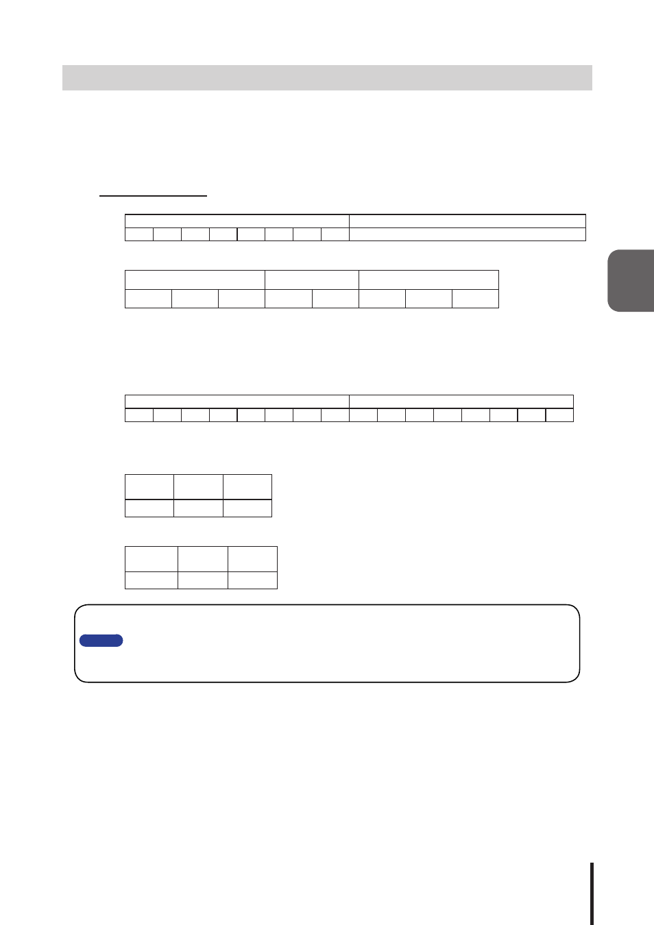
Writing Command
Transmitting the following data controls the Signal Tower and buzzer.
"W" (57H)
Operation Data 8 Bits
0
1
0
1
0
1
1
1
Reference of Operation Data Contents
Details of Operation Data
Signal Tower Flashing
Buzzer
Signal Tower Lighting
Green
Amber
Red
Pattern2 Pattern1
Green
Amber
Red
[Example of sending the writing command transmission]
To operate the Signal Tower with a "red lighting, amber flashing, green lighting, and buzzer pattern2",
enter into the operation data a "1" bit to make it turn ON and a "0" bit to make it turn OFF.
[Command]
"W" (57H)
Operation Data (55H)
0
1
0
1
0
1
1
1
0
1
0
1
0
1
0
1
Response from this product
Normal response (output response)
“A”
(41H)
"C"
(43H)
"K"
(4BH)
1 Byte
1 Byte
1 Byte
Response Error (output failed)
“N”
(4EH)
“A”
(41H)
"K"
(4BH)
1 Byte
1 Byte
1 Byte
Please
In case lighting and flashing are simultaneously turned on by a PHN command, priority is given to
the lighting command.
In case buzzer patterns are turned on simultaneously, priority is given to the pattern1 command.
For further details regarding the PHN Series, please contact your nearest PATLITE Sales
Representative.