Alarm relay 1, Alarm relay 2 – LumaSense Technologies INNOVA 1314i User Manual
Page 68
Chapter 5
______________________________________________________________________
_____________________________________________________________________________
BE6030-13
1314i Photoacoustic Gas Monitor
LumaSense Technologies A/S
Page 68 of 199
The user can switch off the beeper and the message by pressing
INFO or RESET push-button on the front-panel of the Monitor.
The alarm relays will continue being activated until either (1) all
measured gas concentrations fall below their user-defined alarm
level(s); or (2) the monitoring task is stopped – this automatically
closes the alarm relays.
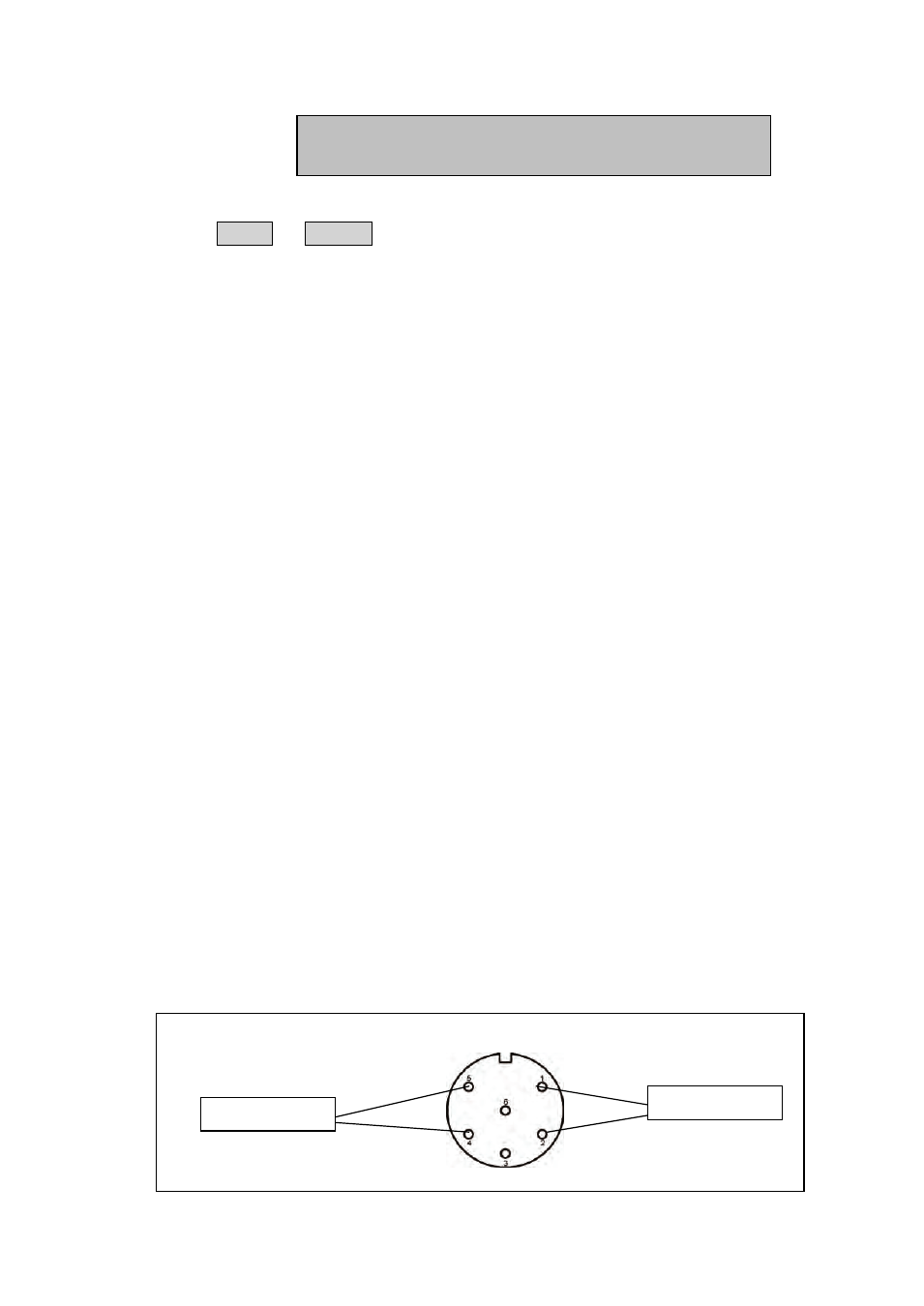
Alarm Relay 1:
Alarm Relay 1: correspond to High Alarm Limit 1.
Whenever one or more gases exceed their alarm level(s) for high
alarm limit 1, the Monitor breaks the electrical connection
between pins 1 & 2 and this activates the attached alarm system.
Alarm Relay 2:
Alarm Relay 2: correspond to High Alarm Limit 2.
Whenever one or more gases exceed their alarm level(s) for high
alarm limit 2, the Monitor breaks the electrical connection between
pins 4 & 5 and this activates the attached alarm system.
LumaSense supplies a 6-pin DIN plug (male) with a locking collar
JP0600 for connecting external alarm devices to the alarm relay.
Caution:
The DC voltage across the relay contacts must not exceed 25V. The
potential on the relay contacts must not be more than 25VDC above
chassis potential, as this will cause an excessive leakage current. The
current through the contacts must not exceed 100mA. AC voltages
must not be connected to the Alarm Relay socket.
Fig.5.2 Configuration of the pins in the alarm relay socket
WARNING:
ALARM LIMIT EXCEEDED
Alarm relay 1
Alarm Relay 2