LumaSense Technologies SpyGlass Lens ViewPort User Manual
Introduction, Installation steps
SpyGlass
TM
Lens ViewPort
Installation Guide
Introduction
This installation kit provides the necessary tools to quickly and efficiently install LumaSense’s MIKRON brand
SpyGlass
TM
Lens ViewPorts into cabinet doors that have steel or aluminum panels up to 16 gauge (2 mm) thick.
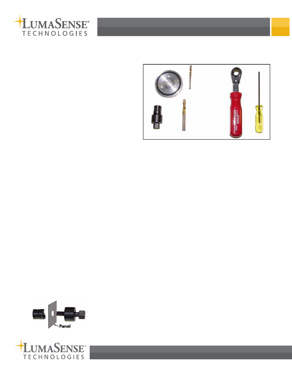
Included Tools
1. ViewPort drill fixture
2. 5/8 inch panel punch (Greenlee)
3. 1/4 inch drill bit for punch pilot hole
4. 5/32 inch drill bit for viewport screws
5. Ratchet box wrench to drive the punch
6. Hex driver for viewport screws
Extra Tools Required (Not Supplied with the Kit)
1. Electric drill
2. Standard Pliers
1
2
4
3
5
6
Installation Steps
1. Consult the instructions included with your
SpyGlass Lens ViewPort to determine the optimal
location to install the ViewPort.
2. Use the ViewPort drill fixture (1) to determine
whether the selected location will interfere with
any panel obstructions (stiffener rails, handle
hardware, etc.). The drill fixture is the same
diameter as the ViewPort’s removable cover.
Use the drill fixture to verify optimal ViewPort
positioning on both sides of the door or panel
before drilling.
3. Hold the drill fixture at the desired location with
the O-Ring facing away from the panel.
4. Use the 1/4 inch drill bit (3) and the center hole of
the drill fixture to mark the panel starting point.
5. Remove the drill fixture and drill a 1/4 inch hole at
the marked location.
6. Separate the punch (2) into two pieces by
unscrewing the smaller diameter piece.
7. Insert the punch bolt through the 1/4 inch hole
and attach the second punch half to the bolt.
(Follow the directions provided with the punch.)
8. Use the ratchet box wrench (5) to tighten the
punch bolt until the punch breaks through the
panel. There should now be a clean 5/8 inch hole
in the panel.
9. Separate the punch and remove the punched
panel circle from the punch bolt.
10. Insert the drill fixture, with O-Ring facing the
panel, into the punched hole.
11. Use the 5/32 inch drill bit (4) to drill the three
mounting holes. Be sure to apply pressure to the
drill fixture while drilling each mounting hole.
Be careful not to allow the drill fixture to rotate
when drilling the mounting holes. (The O-Ring
will provide friction to help prevent the fixture
from rotating while marking/drilling the holes.)
12. Remove the drill fixture.
13. Install the SpyGlass Lens ViewPort according to the
ViewPort instructions.
LumaSense Technologies, Inc., reserves the right to change the information in this publication at any time.
©2012 LumaSense Technologies. All rights reserved.
SpyGlass Lens ViewPort Installation Guide
PN: #512-0002-01 Rev. A 02/21/12
3301 Leonard Court
Santa Clara, CA USA
Ph: +1 800 631 0176
Fax: +1 408 727 1677
[email protected]
www.lumasenseinc.com