LumaSense Technologies MCS320 Quick Start Guide User Manual
Introduction, Unpacking and inspection, Connections
MC320 & MCS640 Quick Start Guide
Introduction
The Lumasense MCS640 and MC320 series IR thermal
imagers are designed to allow users to quickly be up
and running to gain valuable insight into your thermal
processes.
The MC320 is a high performance
non-contact infrared imager that
produces superior images and
temperature measurement (±2 °C)
for both long and mid-wave applica-
tions.
The MCS640 is a short wavelength
infrared (SWIR) thermal imager
with internal digital signal process-
ing. This imager is designed to
accurately measure temperatures
between 600 and 3000 °C.
Caution: Because the camera system is designed for specific
application situations, it is imperative that you configure your
system in accordance with the electrical diagrams supplied with
your system.
Unpacking and Inspection
When unpacking and inspecting your system compo-
nents, you need to do the following:
1. Check all materials in the container against the
enclosed packing list.
2. Carefully unpack and inspect all components for vis-
ible damage.
3. Save all packing materials, including the carrier’s
identification codes, until you have inspected all
components and find that there is no obvious or
hidden damage.
If you find damage, contact the carrier and LumaSense
Technologies.
Connections
In order for the MC320 or MCS640 system to operate cor-
rectly, the supplied hardware must be properly connected
to the computer and power supplied to the various parts
of the system.
In addition, the MC320 and MCS640 cameras are a Giga-
bit Ethernet cameras. In order to ensure all frames are
transferred and reconstructed successfully, the following
hardware needs to be used at minimum:
• Cat 5e or Cat 6 network cable
• Network card with 1.0 Gbps transfer rate
• i3, i5 or i7 CPU
• Accelerated video adapter (ATI, Nvdia etc.)
• Video card must support Jumbo Frames
• Windows XP, Vista, 7, or 8 operating system
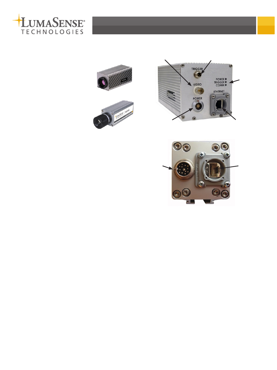
Connection Locations
Connecting the Power Cable
Insert the power cable into the DC In terminal located on
the rear panel of the camera. Alternatively, the MC320
series cameras can be powered via a PoE (Power-over-
Ethernet) capable Ethernet switch. In this case, the power
connection can be left open.
Connecting the Video Output
(MC320 only)
A standard NTSC or PAL monitor can be directly con-
nected to BNC video output connector. The default
setting in the camera is NTSC standard, but it can be
configured to PAL standard via the software.
1. Remove the cap over the Video terminal.
2. Connect the video cable.
3. Twist to lock the connector into place.
Connecting the Ethernet Cable
Typically, the system is set up by either connecting the
camera to a network device (switch) or by connecting the
camera directly to a dedicated computer using a cross-
over Ethernet cable.
MC320 Rear Panel
MCS640 Rear Panel
DC Power
Input
DC Power
Input
Gigabit
Ethernet
Gigabit
Ethernet
Status
LEDs
Trigger Input
Analog
Video Output