Output 3 wiring, 12 output 3 wiring, Ac outputs – Watlow Series 998 User Manual
Page 24: Switched dc, Process retransmit, External transmitter power supply
Installation and Wiring, Chapter 2
2.12
WATLOW Series 998 User’s Manual
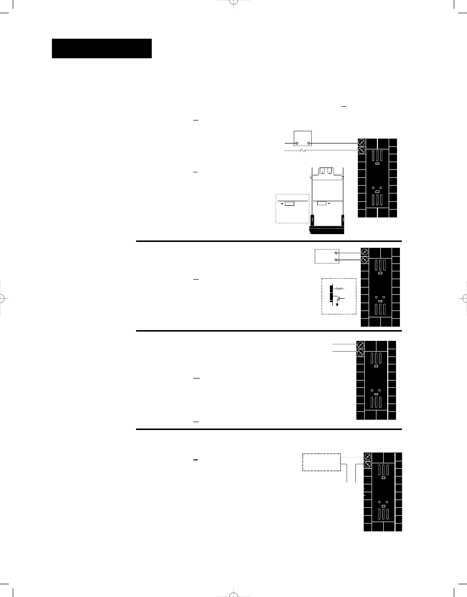
Figure 2.12a
— AC Outputs
•
Solid-state Relay with
Contact Suppression
0.5 Amps
Off-state impedance: 20K
Ω
min.
99 _ _ - _ _ _ _ - B _ _ _
• Electromechanical Relay without
Contact Suppression
Form A or B, 5 Amps
Off-state impedance: 31M
Ω
99 _ _ - _ _ _ _ - J _ _ _
Figure 2.12b
— Switched DC
Minimum load resistance: 500
Ω
99 _ _ - _ _ _ _ - C _ _ _
Figure 2.12c
— Process Retransmit
0-20mA, 4-20mA
Load impedance: 600
Ω
max.
99 _ _ - _ _ _ _ - M _ _ _
0-5V
О
О
, 1-5V
О
О
or 0-10V
О
О
(dc)
Load impedance: 500
Ω
min.
99 _ _ - _ _ _ _ - N _ _ _
Figure 2.12d
— External Transmitter Power Supply
99 _ _ - _ _ _ _ - T _ _ _
See Chapter 1 for DIP switch location and set-
tings.
Form B
Output 3 Wiring
Form A or B
Alarm Jumper Settings
(Top View)
NOTE:
Input-to-output iso-
lation is defeated
when the external
transmitter power
supply is used to
power a transmitter
connected to input
1 or input 2.
• Solid-state Relay without
Contact Suppression
0.5 Amps
Off-state impedance: 31M
Ω
99 _ _ - _ _ _ _ - K _ _ _
External
Load
COM
L1
L2
Fuse
NO Form A
1
2
NC Form B
or
1
2
External
Load
-
+ V
Î
Internal Circuitry
1
2
790
Ω
19 to 32V
Î
(dc)
+
1
2
+
-
Form A
1
2
+
-
+V
-V
Transmitter
4-20mA out
Input
1 or 2
+
-