Alarms, Changing the output 3 alarm jumper, Using alarms – Watlow Series 998 User Manual
Page 106
Alarms
Tuning, Alarms and Error Codes, Chapter 7
7.4
WATLOW Series 998 User’s Manual
in manual operation. Note: It cannot be determined which channel is in
the manual mode when both CH A and CH B lights are on. When the
Auto/Manual light is off, the channel is in automatic operation. When the
Auto/Manual key is pressed once the Auto/Manual light will flash. Press
the key again within five seconds to complete the change in operation.
When a sensor fails, the channel associated with the failed sensor switch-
es from automatic to manual operation.
• If [FAIL] is set to [bPLS], and the bumpless transfer conditions are
met, process has stabilized at a power level less than 75% (±5%) for a
two minute period prior to sensor failure, the channel switches to man-
ual operation at the last automatic power level. If the conditions are
not met, the output goes to 0% power (outputs disabled).
• If [FAIL] parameter is set to a specific value (-100% to 100%), the chan-
nel switches to manual at the power selected by the [FAIL] parameter.
When transferring a channel from auto to manual operation, the control
output(s) remains stable (“bumpless”). When transferring from automatic
to manual operation, the output value appears in the lower display. In
the automatic operation the set point appears in the lower display.
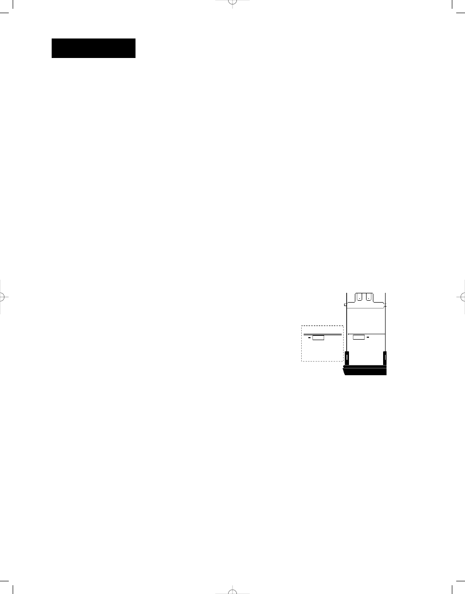
Changing the Output 3 Alarm Jumper
If you have model number 99_ _-_ _ _ _- J _ _ _, output 3 can be config-
ured as a Form A (NO and common con-
tact) or Form B (NC and common contact)
alarm. To change the alarm jumper:
1. Remove the control from the case.
Release the two tabs on one side of the
control, then release the two tabs on the
opposite side. You may need to rock the
bezel back and forth several times to
release the chassis.
2. Set the jumper to the position you want.
See below for jumper location.
3. Return the control chassis to the case. Be sure you have it oriented
correctly. Press firmly, but gently, to seat the chassis.
When you select Form A, the contact is open when power is removed
from the control. When selecting Form B, the contact is closed when
power is removed.
Using Alarms
Output 3 and/or 4 of the Series 998 can be selected as alarms. This is
accomplished in the Output Menu under the [`Ot3] or [`Ot4] prompt. If
[`AL3] or [`AL4] is selected, the output is energized in the non-alarm
condition and de-energizes the output in the alarm condition. Selecting
[AL3n] or [AL4n] reverses this action; the output is then de-energized in
the non-alarm condition and energized in an alarm condition.
Figure 7.4 -
Alarms Jumper
Location.
Form B
Form A
Top View