Channel a input wiring, Thermocouple, Rtd, 2- or 3-wire – Watlow Series 998 User Manual
Page 20
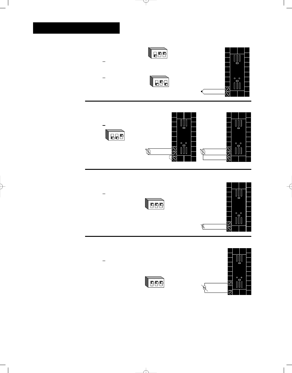
Figure 2.8a
— Thermocouple
Thermocouple only
99 _ _ - 1 _ _ _ - _ _ _ _
Universal signal conditioner
99 _ _ - 2 _ _ _ - _ _ _ _
Figure 2.8b
— RTD, 2- or 3-wire
Universal signal conditioner
99 _ _ - 2 _ _ _ - _ _ _ _
Figure 2.8c
— 0-5V
О
О
, 1-5V
О
О
or 0-10V
О
О
(dc) Process
Universal signal conditioner
99 _ _ - 2 _ _ _ - _ _ _ _
Input impedance: 10K
Ω
Figure 2.8d
— 0-20mA or 4-20mA Process
Universal signal conditioner
99 _ _ - 2 _ _ _ - _ _ _ _
Input impedance: 7
Ω
Installation and Wiring, Chapter 2
2.8
WATLOW Series 998 User’s Manual
NOTE:
Model number
99_ _-1 _ _ _-_ _ _ _
has no input 1 DIP
switch.
Jumper 9 to 10
for 2-wire RTD
9
10
+
-
9
10
8
S2
S1
S3
9
10
8
S2
S1
10
9
-
+
V
DC
10
8
-
+
m
A
NOTE:
Using a grounded
thermocouple for
both input 1 and
input 2 can cause
ground loop prob-
lems.
O
N
↑
1
2
3
O
N
↑
1
2
3
J, K, T, N, C, E, Pt2, D
Dip Switch Setting
R, S, B
Dip Switch Setting
O
N
↑
1
2
3
Dip Switch Setting
O
N
↑
1
2
3
Dip Switch Setting
O
N
↑
1
2
3
Dip Switch Setting
Channel A Input Wiring
ç
CAUTION:
An external resistor
is required for
0-20mA and 4-20mA
process wiring to
prevent a high in-
rush current which
could burn out the
controller’s 7-ohm
resistor. See page
2.4. for recommen-
dations.