Connections overview for gen2 midbus probe, Connection procedure – Teledyne LeCroy Summit T24 PCIe Multi-lane Protocol Analyzer User Manual User Manual
Page 26
Teledyne LeCroy
Using Probes
14
Summit T24 PCI Express Multi‐Lane Protocol Analyzer User Manual
Figure 3.10: Clock Cable
Connections Overview for Gen2 MidBus Probe
Use a 1‐pod setup.
Use the
iPass x4 to x8 Straight cable
to connect the probe data connectors on the Analyzer
to the MidBus pod(s).
On the other side of the pod, connect the MidBus probe assembly.
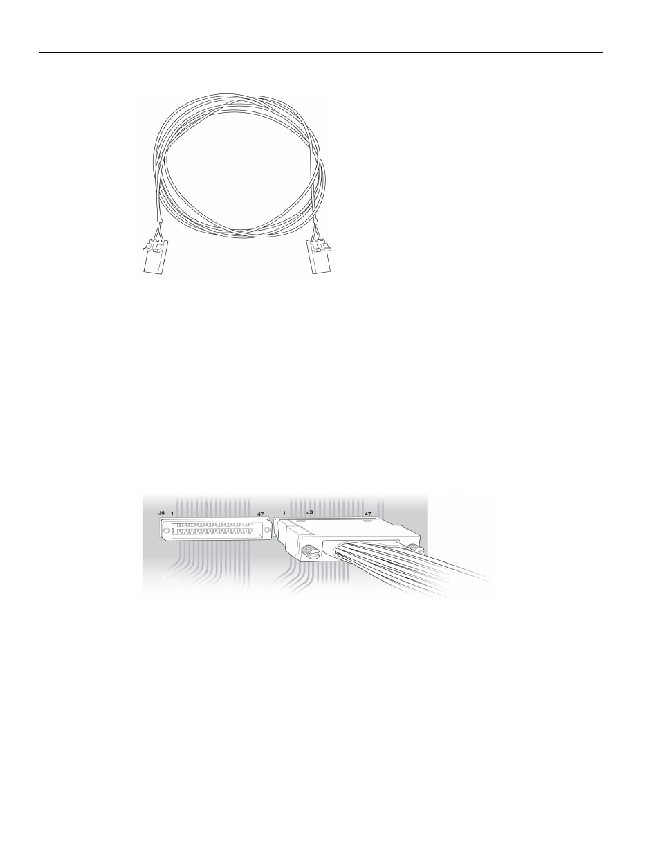
Connect the header on the MidBus probe assembly to the MidBus footprint on the
System Under Test (host platform/root complex). The following picture shows two
midbus footprints, with one connected to the MidBus probe assembly.
Figure 3.11: Connect MidBus Probe to MidBus Footprint
Connection Procedure
To connect the Summit T24 to the System Under Test (host platform/root complex):
1. Connect the MidBus pods to the Analyzer using the
iPass x4 to x8 Straight cable
.
2. Connect the MidBus probe assemblies to the MidBus pods.
3. Connect the MidBus probe assemblies to the MidBus footprints on the system
under test.
4. Connect external reference clock signal to Mid‐Bus External Clock In on Mid‐Bus
probe pod, using external reference clock cable.