3 control signals, control data – IAI America ACON-SE User Manual
Page 58
48
4. Description of Operating Functions
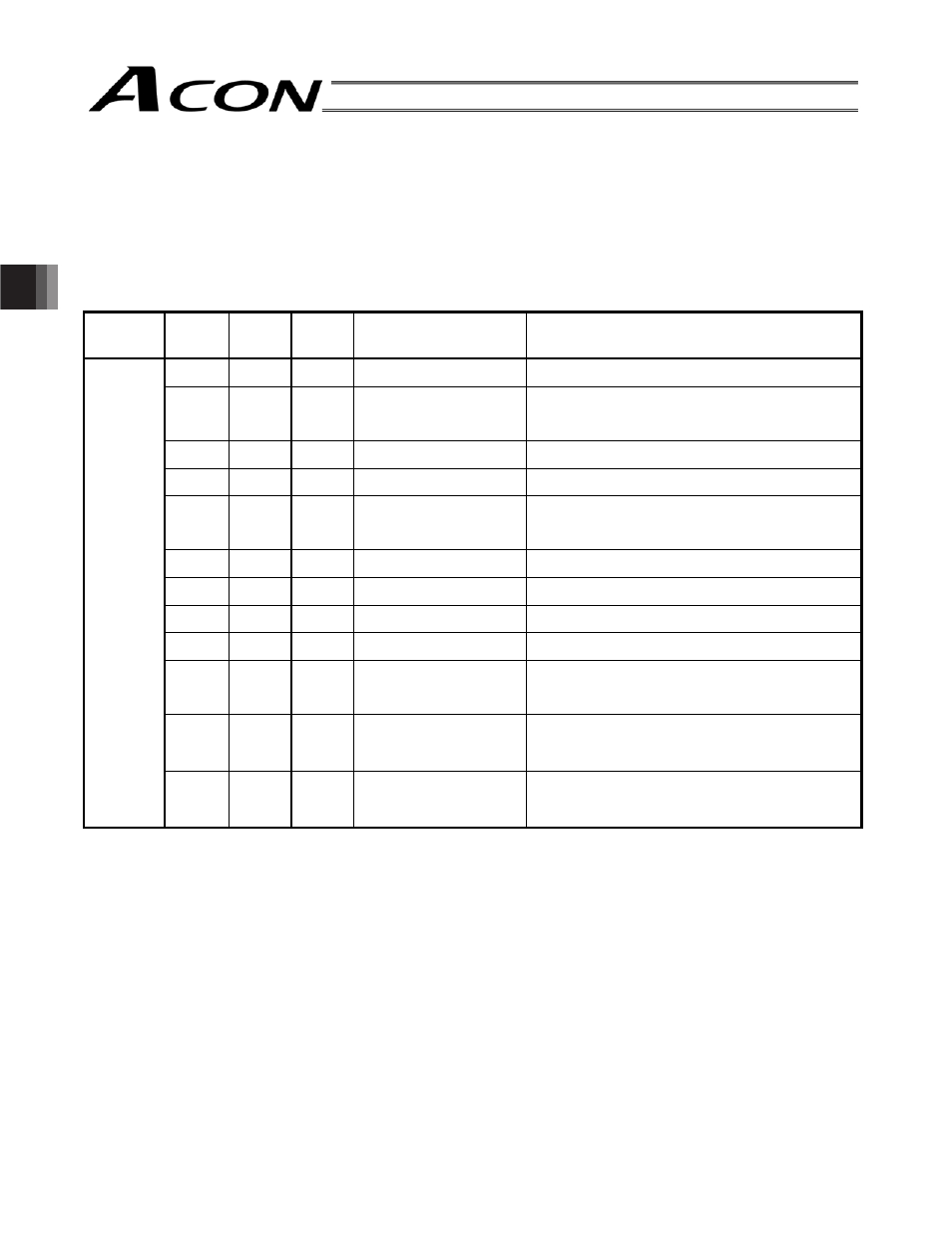
4.3 Control Signals, Control Data
In order to operate ACON-SE via serial communication, it is required to write/read the 16-bit internal memory
(Modbus register, Modbus status) of the controller. The main signals and their symbol names handled at that time
are shown below.
For details, refer to the serial communication operation manual for your ROBO Cylinder series.
(1) Controller Input Signals
(PLC
o Controller)
Register
Bit
address
Bit
position
Signal
symbol
Signal name
Description
15
0401H 14 SFTY
Safety speed command Safety speed set with the parameter
0: Invalid, 1: Valid
13
0403H 12 SON
Servo ON command
0: Servo OFF, 1: Servo ON
±
0407H 8 RES
Alarm reset
1RUPDO³´o³´ULVHHGJH$ODUPUHVHW
7
6
Device
control
register
DRG1
Address
0D00H
040AH 5 STP
Pause command
0: Normal, 1: Pause (deceleration stop)
040BH 4 HOME
Home return command ³´ o³´ULVHHGJH+RPHUHWXUQRSHUDWLRQ
040CH 3 CSTR
Positioning start
1RUPDO³´o³´ULVHHGJH3RVLWLRQLQJVWDUW
to the target position specified with the position
no.
[Common]
*1
2
0
*1 The meanings of [Common], [POS specification] and [Numeric specification] are as follows:
y [Common]:
Used in common in both operation by position number specification and operation by
numeric specification.
y [POS specification]:
Used in the operation by position number specification
y Numeric specification]: Used in the operation by the numeric specification