4 sio converter (option) – IAI America ACON-SE User Manual
Page 31
21
6SHFL¿FDWLRQV
2.4 SIO
Converter
(Option)
Model: RCB-TU-SIO-A (vertical installation)
RCB-TU-SIO-B (horizontal installation)
This unit is a RS232C-RS485 converter.
If multiple controllers are linked, you can connect a teaching pendant to the mini DIN, 8-pin connector to move, or
edit parameters, for all axes.
Ɣ Description
of
Functions
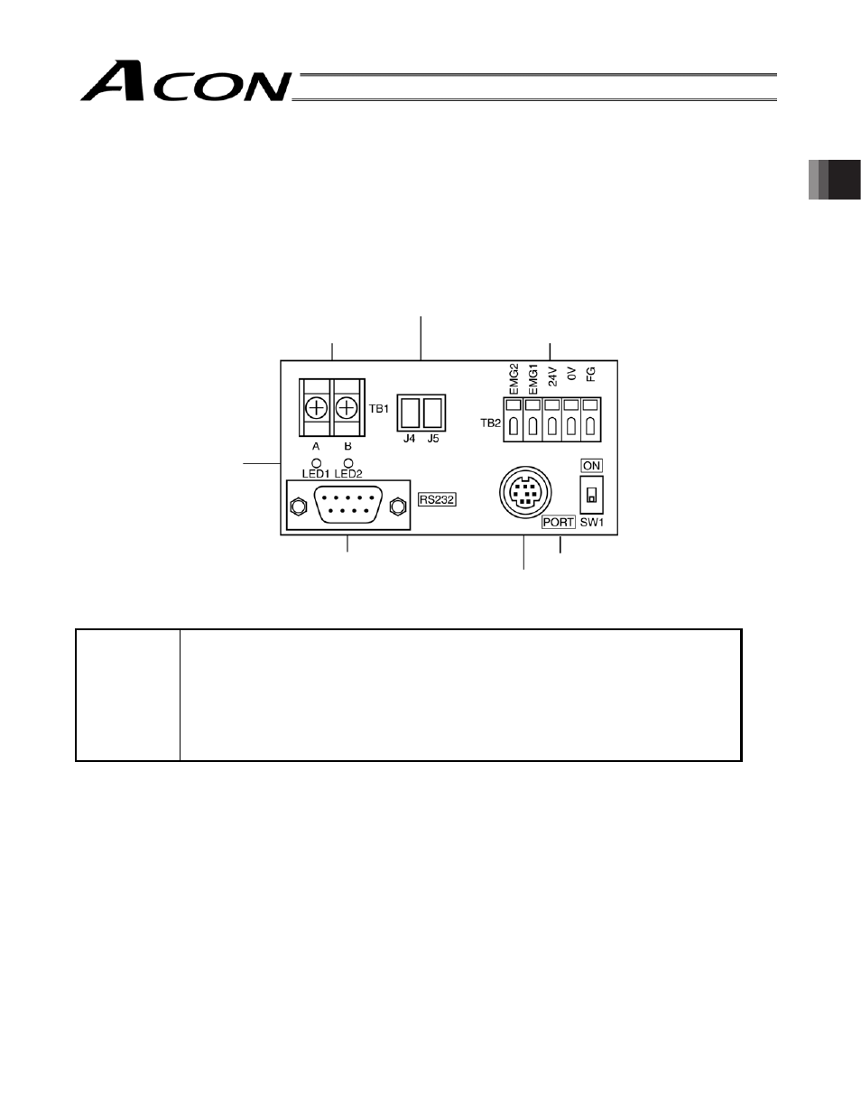
[1] Power/emergency stop terminal block (TB2)
EMG1, EMG2 Provide a contact output for the emergency-stop switch on the teaching pendant
(RCM-T/E). EMG1 and EMG2 connect to the emergency-stop switch on the teaching
pendant when the PORT switch is ON, or are shorted when the PORT switch is OFF.
These terminals comprise an interlock with a safety circuit provided by the user.
24V
Positive side of the 24V power supply (power supply for the teaching pendant and
conversion circuit, power consumption: 0.1A or less)
0V
Negative side of the 24V power supply
FG
FG of the 24V power supply
[2] Link-connection terminal block (TB1)
A connection port for linking the controller.
³$´RQWKHOHIWVLGHFRQQHFWVWR6*$OLQHFRORURUDQJHUHGRIWKHUHOD\FDEOH
³%´RQWKHULJKWVLGHFRQQHFWVWR6*%OLQHFRlor: orange/black 1) of the relay cable.
(Note) Be sure to use twisted pair wires for the above two connections (SGA/SGB).
[3] Link-connection connector (J4, J5)
An e-con connection port for linking the controller. The optional link cable (CB-RCB-CTL002) can be
connected to this port directly. However, J4 and J5 allow only two-axis connection. When connecting three or
more axes, use the terminal block of [2].
[1] Power/emergency stop terminal block (TB2)
[2] Link-connection terminal block (TB1)
[3] Link-connection connector (J4, J5)
[7] Monitor LEDs
[4] D-sub, 9-pin connector
[6] PORT switch
[5] Mini DIN, 8-pin connector