IAI America ACON-SE User Manual
Page 47
37
3. Installation and W
iring
Apply pressure.
Locking tab
Cable tube
Double shielded twisted-pair shielded
Solder
Shielded
wires
Vinyl wire
e-CON connector
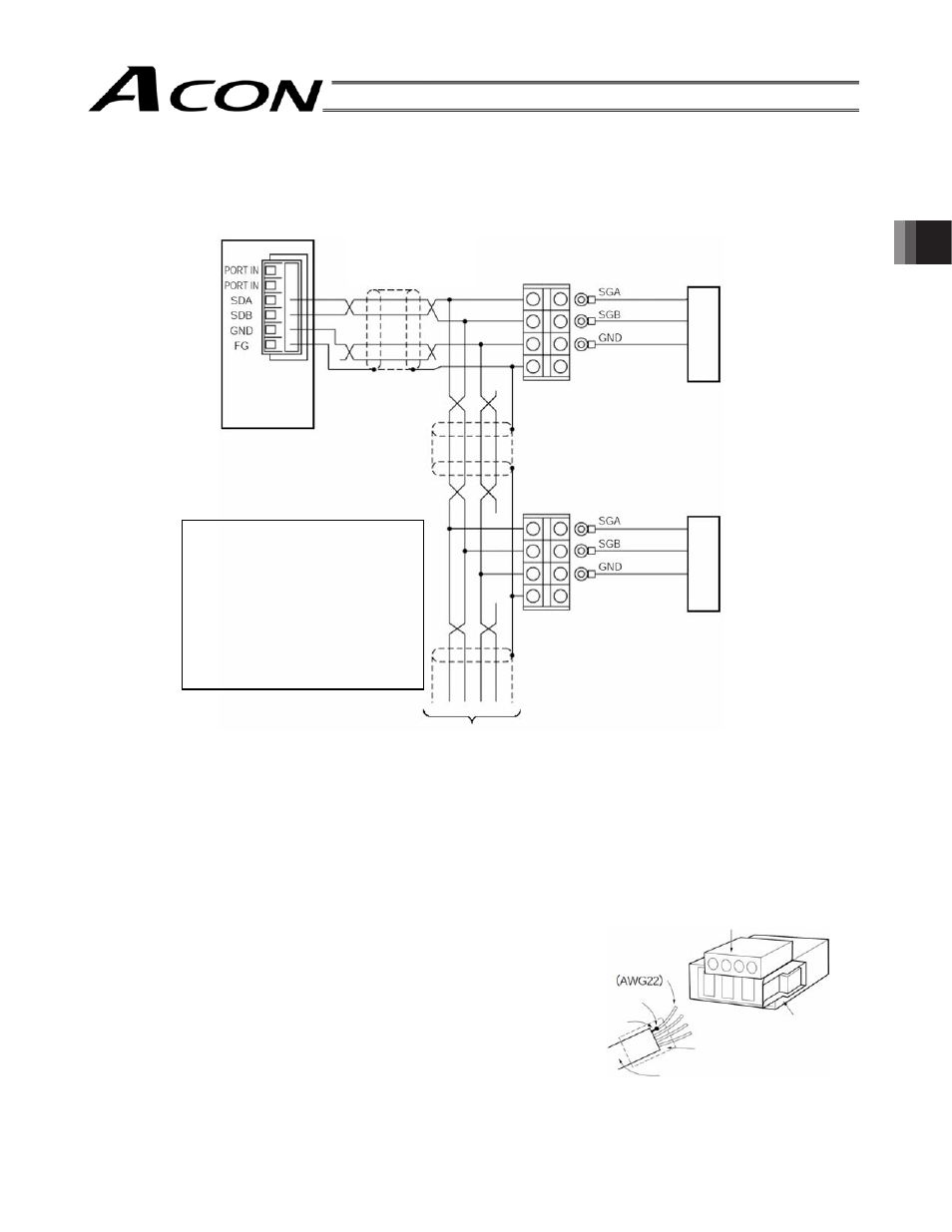
䕔 Detail Connection Diagram
[Connection by Terminal Block or Joint]
* The user must provide relay terminals. Also, connect a terminal resistor (220
:, 1/4 W) between the SGA and
SGB terminals.
Do not ground the end of the main communication line, but terminate it using a terminal block or leave the end
open without any termination.
Ŷ
Preparation of Communication Main Line
[Wiring by Connector]
[1] Strip the sheath of a double shielded twisted-pair cable by
approx. 15 to 20 mm.
[2] Twist the shield wires and solder them onto vinyl wires of
AWG22 (outer diameter 1.35 to 1.6 mm) or equivalent.
[3] Place a cable protection tube over the cable.
[4] Insert the four wires into the cable insertion holes in the
connector (SDA, SDB, GND, FG) without stripping the core
sheath.
[5] With the cable inserted in the press-fit cable housing, apply
pressure from above to pressure-weld the core wires.
[6] Heat-treat the cable protection tube.
Gateway Unit
Double shielded
twisted-pair cable
Recommended cable:
HK-SB/20276 X L
2P X AWG22 by Taiyo
Electric Wire & Cable
Yellow
Orange
Blue
Yellow
Orange
Blue
If installing a terminal block is
difficult or any other wiring
limitation applies, connect the
cable directly using a joint, instead
of using a terminal block.
Connect each wire using a round
crimp terminal with a screw/nut,
and then wrap an insulation tape
around the connection point.
Axis 1
Axis 2
To axis 3