9 connecting the actuator, 32 3. installation and w iring – IAI America ACON-SE User Manual
Page 42
32
3. Installation and W
iring
Cable color
Signal name
Pin No.
Pin No.
Housing: DF1E-3S-2.5C (Hirose)
Contact: DF1E-2022SC
(Hirose)
(or
DF1B-2022SC)
Housing: SLP-03V (J.S.T. Mfg.)
Contact: BSF-21T-P1.4
(J.S.T.
Mfg.)
Wire size
Pin assignments
Controller end
Pin assignments
Actuator end
Cable model marking
(
9)
Pin No.
Cable color
Standard cable
Robot cable
Description
White/Purple
White/Grey
Yellow
Blue
White/Blue
White/Yellow
White/red
White/Black
Orange
Green
Purple
Grey
Red
Black
Drain
Blue
Orange
Green
Brown
Grey
Red
Black
Yellow
Pink
Purple
White
Blue/Red
Orange/White
Green/White
Drain
Pin No.
Home check
sensor
Brake power
Encoder phase
A signal
Encoder phase
B signal
Encoder phase
Z signal
Encoder control
Encoder power
signal
Shield
Housing: PHDR-18VR (J.S.T. Mfg.)
Contact: SPHD-001T-P0.5 (J.S.T. Mfg.)
Housing: XMP-18V (J.S.T. Mfg.)
Contact: BXA-001T-P0.6 (J.S.T. Mfg.)
Retainer: XMS-09V (J.S.T. Mfg.)
Pin assignments
Controller end
Pin assignments
Actuator end
Cable model marking
Signal
name
Signal
name
(
10)
3.9 Connecting
the
Actuator
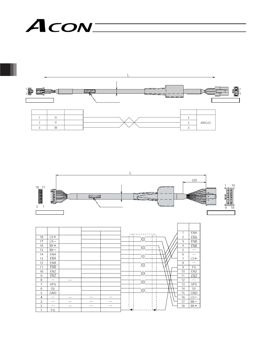
Dedicated relay cables are used to wire between the controller and actuator.
(1) RCA motor cable
Model: CB-ACS-MA
CB
(
indicates the cable length L. Example: 080 = 8 m)
(2) RCA encoder cable/encoder robot cable
Standard cable model: CB-ACS-PA
Robot cable model: CB-ACS-PA-
-RB (optional)
(
indicates the cable length L. Example: 080 = 8 m)
Red
White
Black