6 wiring the power supply – IAI America ACON-SE User Manual
Page 37
27
3. Installation and W
iring
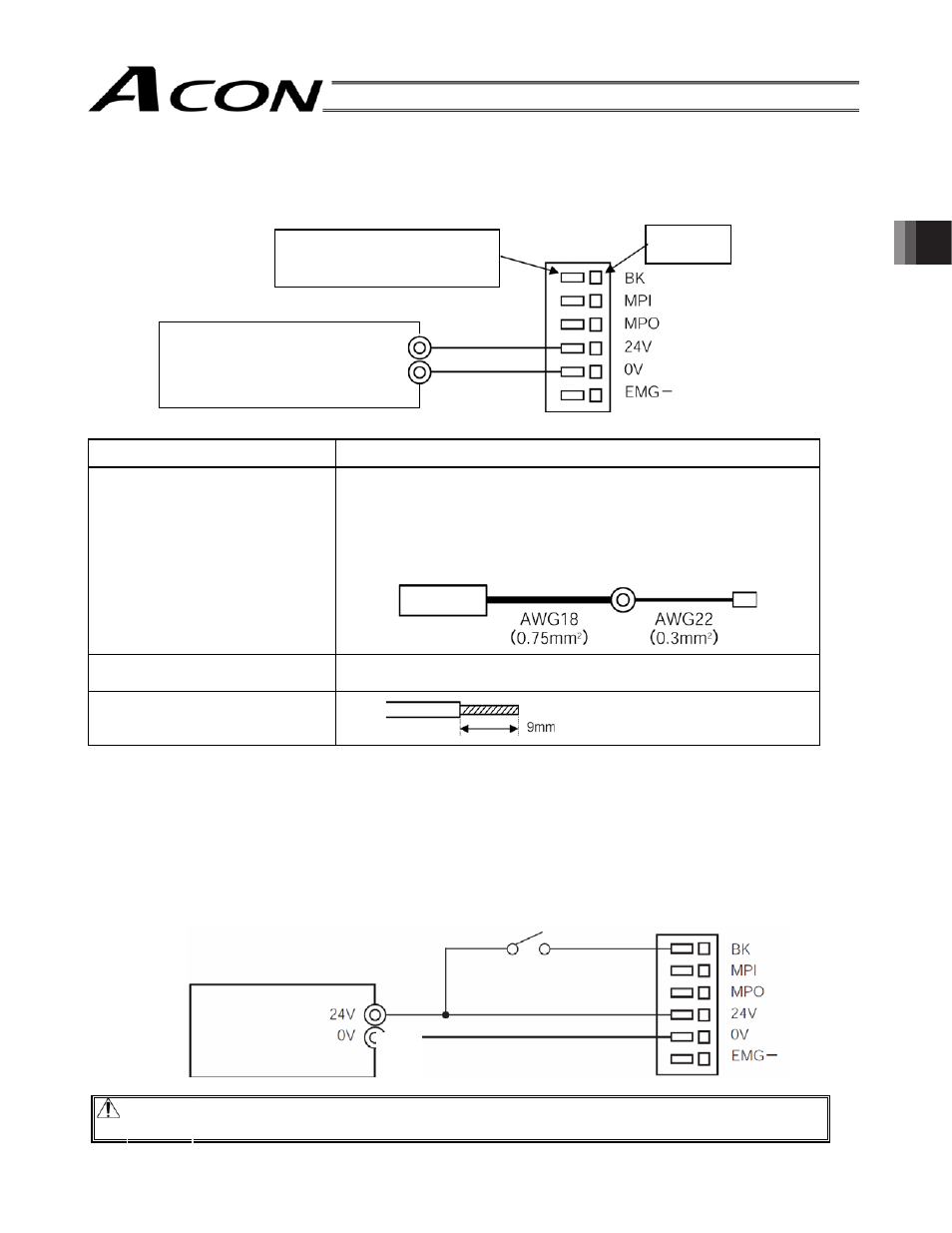
Brake release switch to
forcibly release the brake
Power supply
terminal block
Input power supply:
24 VDC:
3.6 Wiring the Power Supply
Connect the +24V side of the 24 VDC power supply to the 24V terminal on the power supply terminal block and
the 0V side to the 0V terminal.
Use a power cable satisfying the following specifications:
Item
Description
Applicable wire
Twisted wire: AWG size 22 (0.3 mm
2
) (copper wire)
(Note) Pay attention to terminal treatment to avoid a short
circuit resulting from chips.
If the wire path is long, install a relay terminal block and
change the wire size.
Insulating sheath temperature
rating
60
qC or more
Stripped wire length
3.7 Wiring the Brake Release Switch to Forcibly Release the Brake
If the actuator is equipped with a brake, install the brake release switch for resetting at startup adjustment or in an
emergency.
The switch (24 VDC, contact capacity 0.2 A or more) must be prepared by the customer.
Connect one side of the switch to the positive side of the 24 VDC power supply and the other side to the BK
terminal on the power supply terminal block.
The brake will be released by closing the switch.
Danger: In the case of a vertical axis, release the brake while exercising caution to avoid hands from
being caught and the robot hand or work from being damaged due to a sudden drop.
Input power supply:
24V
24 VDC:
0V
Open the cable inlet by pushing
it with a flathead screwdriver.
Power supply
terminal block
Cable inlet
Input power
supply
Power supply
terminal block
Relay terminal block