Destruct – Teledyne 9110TH - Nitrogen Oxides Analyzer User Manual
Page 50
Model 9110TH NOx Analyzer
Getting Started
Teledyne Analytical Instruments
30
VACUUM
PRESSURE
SENSOR
SAMPLE
PRESSURE
SENSOR
O3
FLOW
SE
N
S
OR
FLOW PRESSURE
SENSOR PCA
INSTRUMENT CHASSIS
PERMAPURE
DRYER
NO/NO
X
VALVE
AUTOZERO
VALVE
O
3
GENERATOR
SAMPLE
GAS
INLET
Fil
ter
Orifice Dia.
0.004"
PUMP
NO
X
E
x
ha
us
t
Scr
u
b
b
er
O
3
Destruct
EXHAUST
GAS
OUTLET
EX
HA
US
T M
A
NIF
O
LD
Orifice Dia.
0.007"
Orifice Dia.
0.007"
REACTION
CELL
PMT
NC
COM
NO
NC
COM
NO
NO
2
Converter
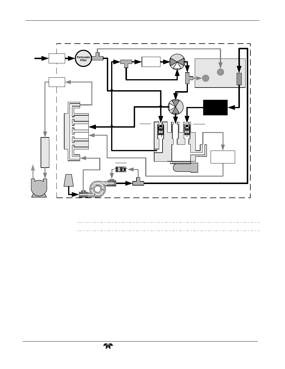
Figure 3-16:
9110TM Internal Pneumatic Block Diagram - Standard Configuration
Note
Pneumatic Diagrams do not reflect the physical layout of the instrument.
The most significant differences between the 9110TH and 9110TM versions in regards
to pneumatic flow are:
A bypass line leading directly from the particulate filter to the exhaust
manifold is present on the 9110TH, but not in the 9110TM.
The diameter of the critical flow orifice controlling the gas flow into the
sample chamber is smaller and therefore the flow rate of sample gas through
the instrument is lower.
- 1220 - Multipoint flammable gas and vapor detection system (50 pages)
- 212R - Thermal conductivity analyzer (28 pages)
- 235 - Thermal conductivity analyzer (38 pages)
- 275R - Portable turbine generator purge gas analyzer (21 pages)
- 2000A-EU - General purpose thermal conductivity analyzer (86 pages)
- 2000XTC - Thermal conductivity analyzer (40 pages)
- 2010A - Split architecture thermal conductivity analyzer (110 pages)
- 2010B - Split architecture thermal conductivity analyzer (98 pages)
- 2020 - Explosion proof thermal conductivity analyzer (80 pages)
- 2120 - Trace Nitrogen in Argon Analyzer (66 pages)
- 2120XL - Trace Nitrogen Analyzer (85 pages)
- 2230R - Process Hydrogen Analyzer (26 pages)
- 2240 – Portable Handheld Hydrogen Leak Detector, 3rd generation (updated 1/31/11) (30 pages)
- 2240 - Portable Handheld Hydrogen Leak Detector, 3rd generation (revision 2/29/08) (40 pages)
- 2240 – Portable Handheld Hydrogen Leak Detector, 2nd generation (13 pages)
- 2750 - Portable turbine generator gas analzyer (40 pages)
- 300P - Percent oxygen analyzer (24 pages)
- 306WA - Analog trace oxygen analyzer (46 pages)
- 311 - Portable trace oxygen analyzer (19 pages)
- 311D - Portable trace oxygen analyzer with digital meter (18 pages)
- 311XL - Portable trace oxygen analyzer (18 pages)
- 316RA / RB / RAD / RBD - Oxygen analyzers (24 pages)
- 319R - Oxygen analyzer (23 pages)
- 320 Series - Portable oxygen detectors (24 pages)
- 326, 327 and 328 - Oxygen analyzers (45 pages)
- 329R - Oxygen analyzer (22 pages)
- 335 - Analog control room monitor for personnel safety (24 pages)
- 356WA - Analog trace oxygen analyzer (42 pages)
- 3000MA - Paramagnetic oxygen analyzer (63 pages)
- 3000MA - Paramagnetic oxygen analyzer Addendum (2 pages)
- 3000MB - Paramagnetic oxygen analyzer (59 pages)
- 3000PA - General purpose percent oxygen analyzer (69 pages)
- 3000PAEU - General purpose percent oxygen analyzer (78 pages)
- 3000PB - Bulkhead mount percent oxygen analyzer (82 pages)
- 3000TA - General purpose trace oxygen analyzer (75 pages)
- 3000TA-EU - General purpose trace oxygen analyzer (89 pages)
- 3000TA-XLEU - Trace oxygen analyzer (108 pages)
- 3000TB - Bulkhead mount trace oxygen analyzer (78 pages)
- 3000TB-XL - Trace oxygen analyzer (78 pages)
- 3000ZA - Trace oxygen analyzer (81 pages)
- 3000ZA-3X - Trace oxygen analyzer (72 pages)
- 3000ZA2G - Zirconium oxide analyzer (72 pages)
- 3000 Ultra Trace - PPB oxygen analyzer (72 pages)
- 3010MA - Paramagnetic oxygen analyzer, includes 0-100% range (88 pages)
- 3010MA – Paramagnetic oxygen analyzer, no 0-100% range – (superceded) (88 pages)